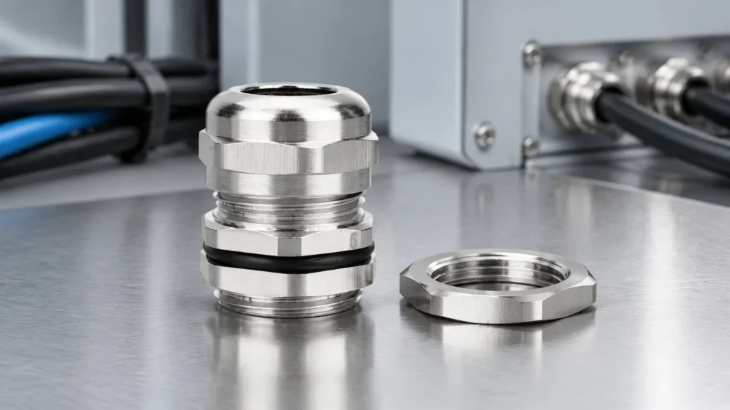
PG13.5 is the most common PG size in the world and the most misunderstood number in cable gland catalogues. Buyers measure the thread, read about twenty point four millimetres, and conclude that they need an M20. Then the M20 gland rattles in the hole, the washer never seals, and the enquiry arrives with a photograph and a complaint.
There is no fault in the gland. There is a convention problem. This page unpacks PG13.5 on its own terms: what the number means, what it fits, and how to decide between keeping PG and converting to metric.
13.5 Is Not a Diameter You Can Measure
PG stands for Panzergewinde, the German conduit thread standardised in DIN 40430. Its size numbers refer to the nominal bore of the thread, effectively the inside diameter the conduit was designed to pass, not the outside diameter you put a caliper on. PG13.5 therefore has a thread outside diameter of twenty point four millimetres.
Once that is clear, everything else follows. PG sizes do not map onto metric sizes by number, they map by outside diameter, and the mapping is deliberately awkward. It is also why a plant with PG panels cannot simply order “the metric equivalent” and expect parts to fit.
The standard itself was withdrawn decades ago, which is worth knowing when a supplier quotes DIN 40430 as if it were current. PG threads remain in service because the installed base is enormous, not because the standard is alive.
PG13.5 in the Context of the PG Family
Seeing the family together explains why PG13.5 became the default. It is the size that covers the ordinary control and power cable band, so it appears on almost every legacy European enclosure.
Size
Cable range
Thread O.D.
Mounting hole
GL
Spanner
PG7
3 to 6.3 mm
12.5 mm
12.5 to 12.7 mm
7 mm
14 mm
PG9
4 to 8 mm
15.2 mm
15.2 to 15.4 mm
8 mm
18 mm
PG11
5 to 10 mm
18.6 mm
18.6 to 18.8 mm
8 mm
20 / 21 mm
PG13.5
6 to 12 mm
20.4 mm
20.4 to 20.6 mm
8 mm
22 mm
PG16
10 to 14 mm
22.5 mm
22.5 to 22.7 mm
9 mm
24 mm
PG21
13 to 18 mm
28.3 mm
28.3 to 28.5 mm
9 mm
30 / 32 mm
Two observations matter commercially. The PG ladder has narrower steps than the metric ladder, so the jump from PG13.5 to PG16 adds only two millimetres of thread and one point five millimetres of cable range, whereas metric goes from M20 straight to M22 and M25. And every PG outside diameter lands on an inconvenient value, which is precisely why existing holes cannot be reused for metric glands.
PG13.5 and M20: Same Cable, Different Hole
The two sizes clamp exactly the same cables. Both cover six to twelve millimetres of sheath diameter, both have the same eight millimetre thread length, and both take a twenty-two millimetre spanner. On paper they are twins.
Property
PG13.5
M20 x 1.5
Cable range
6 to 12 mm
6 to 12 mm
Thread outside diameter
20.4 mm
20 mm
Mounting hole
20.4 to 20.6 mm
20 to 20.2 mm
Thread length GL
8 mm
8 mm
Spanner size
22 mm
22 mm
Thread form
80 degree PG, withdrawn standard
60 degree metric, current standard
The four tenths of a millimetre is the whole story. An M20 gland in a hole drilled at twenty point four millimetres has clearance all round and no reliable sealing face; a PG13.5 gland will not enter a hole drilled at twenty point one. In a panel that was built for one system, the other system does not fit, and no amount of tightening changes that.
The thread form is the second difference, and it is the one that matters after the hole is solved. The flank angle is eighty degrees in PG against sixty in metric, so the threads do not interchange even where the diameters are close. Our guide to PG versus metric cable glands covers the geometry, and the thread size chart has the full cross-family comparison.
Identifying an Unknown Thread in the Field
Most PG13.5 problems are discovered by a maintenance technician holding a gland and an unlabelled hole. Three checks settle it. Measure the thread outside diameter across the crests: twenty point zero points to M20, twenty point four points to PG13.5. The difference is small enough that a cheap caliper read at an angle will blur it, so measure twice.
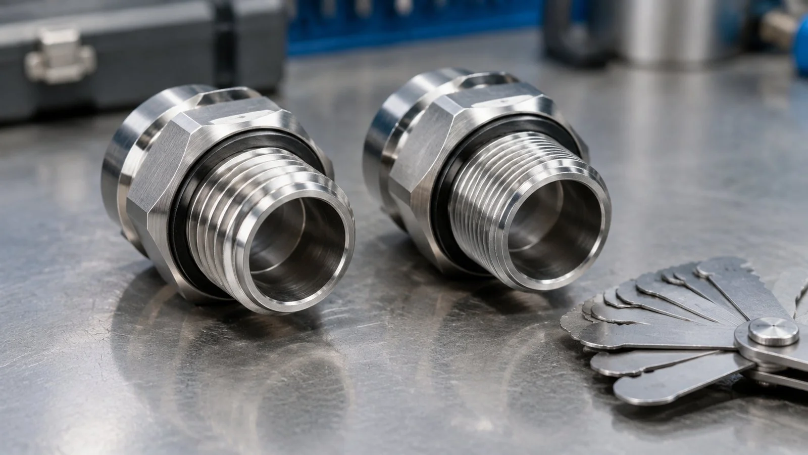
Two glands and a thread gauge: measuring the outside diameter across the crests is the fastest way to separate M20 from PG13.5.
Second, try a known M20 locknut by hand. On a PG13.5 thread it will start, feel loose, and stop within a turn or two because the flank angles differ. That partial engagement is the most misleading symptom in the whole exercise, and it is why glands get forced and threads get destroyed. Third, look for the panel drawing or the original equipment tag, which is faster and more reliable than either measurement.
What must not happen is a gland tightened until it feels right on a thread that never engaged properly. A cross-threaded gland seals nothing and destroys the enclosure thread, converting a five-minute identification into a re-tap.
The Dimensions of PG13.5 in Use
Parameter
PG13.5 standard gland
What to confirm
Cable range
6 to 12 mm sheath diameter
Measured sheath OD, maximum of three readings
Thread outside diameter
20.4 mm
Explains why an M20 hole will not accept it
Mounting hole
20.4 to 20.6 mm
Drill to 20.5 mm when a new hole is being made
Thread length GL
8 mm
Must cover wall plus locknut plus washer
Spanner size
22 mm across flats
Same tool as M20, which is a small mercy
Note the practical consequence of the hole tolerance: 20.4 to 20.6 is a two tenths window like every other size, so a hole drilled at 20.5 works, and a hole drilled at 21 does not seal. The rule does not change with the thread system, only the starting number does. Our cable gland hole size chart covers drilling quality and wall thickness in detail.
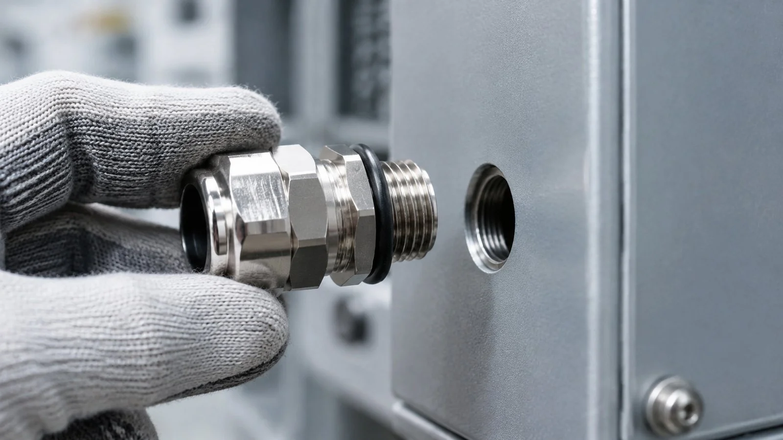
A PG13.5 thread entering its hole: 20.4 to 20.6 mm is the whole tolerance window for this size.
Adapters, Enlargers and Their Real Cost
The usual proposal for a mixed plant is an adapter: a PG13.5 male to M20 female reducing bush, or the reverse. They exist and they work, and they carry three costs that never appear on the quotation.
The first is stack height and spanner clearance. Each adapter adds a component to turn, and a row of entries that fitted before may not fit with adapters between the gland and the panel. The second is a new sealing interface: an adapter adds a thread to be sealed, usually with a different mechanism from the gland. The third is the earth path, because on a metallic enclosure the adapter becomes part of the bonding chain and its material and coating now matter.
Adapters are the right answer for a one-off repair. They are the wrong answer as a standardised design decision across a new panel, where re-drilling and committing to one thread system is cheaper over the life of the installation.
Why PG13.5 Is Still the Right Answer in Places
Converting everything to metric is a tidy ambition that often costs more than it saves. Where an enclosure is already tapped PG, where spare glands and locknuts are held for an existing asset, or where a machine is under OEM warranty, staying with PG13.5 is the engineering answer rather than a compromise.
The decision rule that works: convert when the panel is being replaced or re-drilled anyway, and stay when the thread is cut into cast metal that cannot be reworked. Mixed thread systems are survivable if they are documented, with the thread system marked at each entry rather than assumed.
Stainless and Other Materials in PG13.5
PG13.5 is available in nickel plated brass, in stainless steel and in nylon, and only the thread and the hole are guaranteed to match across materials. Cable range and thread length can differ, so a stainless substitution made on “same PG13.5” is not a like-for-like change.
A supplier will send M20 if the number is approximated
Thread system note
State PG explicitly on the drawing
Prevents a metric substitute in a later batch
Cable range required
Measured sheath OD, for example 9 to 10 mm
Keeps the cable mid-range rather than at a limit
Material and finish
Nickel plated brass, or 316L
Stops unplated brass reaching a wet area
Accessories
Locknut, washer and shroud in PG13.5
An M20 locknut will start and then seize
IP rating with conditions
IP68, 2 m for 24 h
Turns a claim into a specification
If the hole does not exist yet and nothing on site is committed to PG, the honest recommendation is metric. M20 covers exactly the same cable band with a current standard behind it, and our M20 cable gland size guide gives the matching dimensions. The brass cable gland range lists both systems side by side if you need to check availability before deciding.
Frequently Asked Questions
What size hole does a PG13.5 gland need?
Twenty point four to twenty point six millimetres. Drill twenty point five when making a new hole, and remember that a hole already drilled at twenty or twenty point one for an M20 will not accept it.
Is PG13.5 the same as M20?
They clamp the same six to twelve millimetre cables and take the same twenty-two millimetre spanner, but the thread outside diameter differs by four tenths of a millimetre and the thread forms are not compatible.
Can I put an M20 gland in an existing PG13.5 hole?
It will pass through, but it will not seal. The hole is larger than the thread, so the gland has clearance all round and the washer cannot be compressed against a defined face.
Is the PG standard still current?
The DIN standard that defined it has been withdrawn, though PG threads remain in wide service on existing plant. New designs normally specify metric, and PG is used for compatibility with what is already installed.
Does a PG13.5 to M20 adapter solve a mixed plant?
For a repair, yes. As a design standard it adds stack height, a second sealing interface and a component in the earthing path, so re-drilling to one system is usually better over the life of a panel.
Waterproof cable gland play a vital role in modern industries, especially in the B2B sector. They not only ensure the sealing of cable connections, preventing water and dust ingress, but also enhance the overall safety and stability of electrical systems. Did you know that improper installation of cable glands can not only shorten equipment lifespan […]
A practical guide to installing explosion proof cable glands: barrier compound curing, entry thread engagement, tightening criteria and the inspection record that IEC 60079-14 expects.
Strain relief keeps load off the terminals, not off the cable. The three mechanisms, what determines pull-out resistance, and when a gland is not enough.
We use cookies to enhance your browsing experience, serve personalised ads or content, and analyse our traffic. By clicking "Accept All", you consent to our use of cookies.