Waterproof Cable Gland
Waterproof Split Cable Glands Guide
Discover waterproof split cable glands with IP66 IP68 ratings nylon brass stainless steel options ideal for pre-terminated cable installations and retrofitting.
Read More
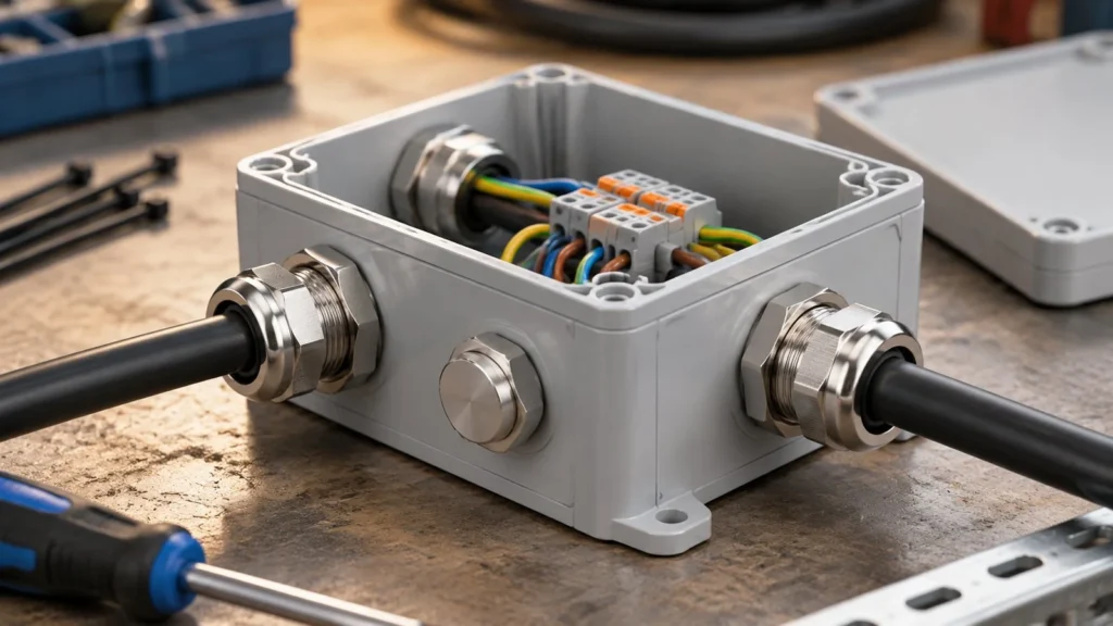
A junction box is where a cable run stops being a cable run and becomes a circuit. That sounds like a trivial distinction, but it changes what the cable gland has to do: the gland is no longer protecting the end of a cable, it is protecting one of several entries into a shared electrical node, and the mechanical load that used to be carried by the enclosure now has to be shared between them.
This guide treats the junction box as a node rather than a container: which gland configurations each type of box needs, who actually carries the cable weight, why two IP ratings do not add up, and why so many boxes leak without a single drop coming through the gland.
The difference is in the cable count and the cable directions. An enclosure usually terminates a run: one cable in, a device inside, no continuation. A junction box joins runs, so it has two or more cables arriving from different directions, often at different sizes, and often with spare ways left for future circuits.
That has two consequences. The entry plan has to be designed as a plan, because the last cable added is the one that breaks a layout that was never generous enough. And the enclosure cannot be treated as a support, because every cable pulling in a different direction loads a different gland, and the sum of those loads is carried by a lid and a thin wall.
| Box function | Typical entries | What governs the gland choice |
|---|---|---|
| Through or draw box | Two, opposite faces | Same size both ends; bend radius rather than seal |
| Branch or tee box | Three or more, different sizes | Each entry sized independently; spare way on the largest |
| Terminal or marshalling box | Many small entries | Density and identification, not cable size |
| Instrument or sensor box | One or two small, screened | Shield termination and small-range inserts |
| Ex junction box | Fixed, certified pattern | Only the entries the certificate lists, in that pattern |
| Buried or below-grade box | Two, on sealed ducts | Immersion rating and a drainage philosophy |
Reading down that table, only one row is governed primarily by the seal. The rest are governed by geometry, density or certification, which is why buying a good gland is rarely the whole answer for a junction box.
Inside a junction box the terminals are not a strain relief. They are sized to carry current and to be tightened once, and a cable hanging from a gland with no other support transfers its weight through the conductor into a terminal screw. The result is a joint that was correct at commissioning and is loose a year later, which then reads as a loose connection rather than a mechanical design error.
The load has to be stopped at the gland, which is what a proper clamping cage does, and the gland in turn has to be stopped by the box. On a light enclosure the third link is the weak one: the wall flexes, the locknut has nothing stiff to bear against, and the whole assembly moves as a unit. A stiffening plate or a gland plate resolves it, and it is much cheaper to add at build than to retrofit. The mechanics of the clamping end are covered in our guide to cable gland strain relief.
The gland projects inward, the cable has to bend immediately behind it, and the terminals sit at a fixed height on the rail. Those three facts interact, and the interaction is why a box that is adequate on paper can be impossible to wire. A thick power cable needs a real bend radius, and if the entry is opposite the terminal block with little depth behind it, the cable arrives at the terminal at an angle and the conductor is stressed for its whole service life.
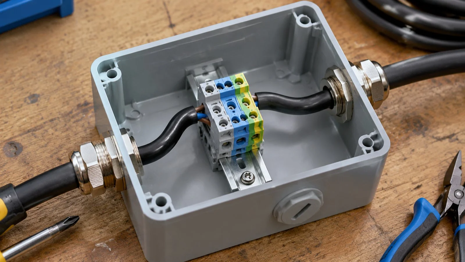
The practical check is to lay the cable out at full size before the box is ordered: entry face, bend, terminal. If the bend does not fit, the answer is a deeper box, an offset entry, or a right-angle gland, in that order of preference. Trying to solve it by bending harder damages the conductor and, on screened cable, distorts the geometry that the shield termination depends on.
A box rated IP66 with glands rated IP68 does not produce an IP68 assembly. It produces a system whose weakest interface governs, and that interface is often the one nobody specified: the lid gasket, the knockout that was punched rather than drilled, or the gap between a gland body and a painted surface.
The correct way to read it is as a chain, where each link is a separate seal:
| Link | What typically breaks it | How it is checked |
|---|---|---|
| Cable to insert | Cable at the top of the range; scored sheath | Measure the sheath; pull test by hand |
| Insert to body | Insert not seated; dome nut bottomed out | Dismantle one gland per batch |
| Body to wall | Knockout lip; paint on the sealing face | Look with the gland removed |
| Wall to lid | Compressed or painted gasket; missing screws | Water test on the assembled box |
The assembly is as good as its worst link, and the gland only controls the first three. This is also why adding a higher-rated gland to a leaky box changes nothing, a pattern covered in our guide to why cable glands leak.
A gland seals against a flat face. A knockout leaves a raised or torn lip, and a moulded plastic box often has a recessed ring around the entry that prevents the body from seating. Both are common on junction boxes and both are invisible once the gland is fitted.
Wall material changes the fixing method more than the seal: ABS and polycarbonate need a flat, unreinforced area and a locknut with a wide bearing face; cast aluminium tolerates more torque but strips suddenly; GRP and sheet steel deflect and need either a plate or a backing washer. The entry planning method in the combiner box entry guide applies to any multi-entry box, including the spacing needed for wrench access.
Most water found inside an outdoor junction box entered as vapour and left as liquid. Air inside the box expands when the sun heats it and is drawn out; when the box cools at night, moist air is drawn back in and condenses on the lid and on cool metal. The gland is working perfectly throughout.
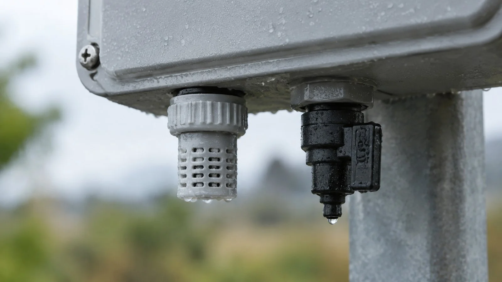
This matters because the standard response, tightening the gland or adding sealant, makes the problem worse by reducing the box’s ability to equalise. The correct responses are a breather element that passes vapour but not liquid water, a drain valve at the lowest point, or a desiccant where the box is genuinely sealed. The installation precautions for waterproof glands include the orientation rules that keep rain out; condensation is the separate half of the same problem.
A junction box without a spare way is a box that will be modified on site. Every field-drilled entry is a hole without a flat face, without a deburr, and without a specified gland, so the cheapest reliability measure available on a junction box is one blanked spare entry per box at the factory.
Marking belongs in the same conversation. Where several cables enter a node, the panel schedule, the cable tag and the gland position have to agree, otherwise the next person to open the box traces cables by hand. A short engraved or printed tag on each entry costs less than one hour of tracing, and it survives the life of the installation in a way that a marker pen does not.
| Field | What to write | Why |
|---|---|---|
| Entry ID | Position and face, matched to the drawing | Makes the box buildable and the service visit easier |
| Cable and OD | Tag plus measured sheath diameter | Sizing follows the sheath, not the conductor |
| Thread and size | Metric or PG, with pitch | A correct gland in the wrong thread still fails |
| Gland type | Standard, screened, or multi-cable | Determines the internal space needed |
| Load path | Where the cable is supported outside the box | Decides whether the gland carries weight |
| Spares | Number of blanked ways | Prevents field drilling later |
Six lines per entry is enough to build the box once and service it for twenty years. The material and thread options referenced here are carried in the nylon and brass ranges, and the wall and fixing rules are set out in the enclosure entry guide.
As many as the entry plan allows with tool access for each. Density, not seal performance, is normally the limiting factor, and the spacing needed for a spanner is usually wider than the spacing that looks tidy on a drawing.
No. The assembly is governed by its weakest interface, so a higher-rated gland does not raise the box rating. Spend the difference on a proper lid gasket and flat entry faces instead.
Condensation, in most cases. Warm moist air enters as the box breathes, then condenses on the lid as it cools. A breather element or drain valve addresses it; tightening the glands does not.
No. Terminals are not strain relief, and the box wall is not a structural anchor. Support the cable outside the box so the gland carries almost no weight, and stiffen the wall where the entries are dense.
Function rather than construction. A junction box joins cable runs and may contain joints; a terminal box brings conductors onto a terminal block for connection to a device. The entry requirements differ mainly in cable count and density.
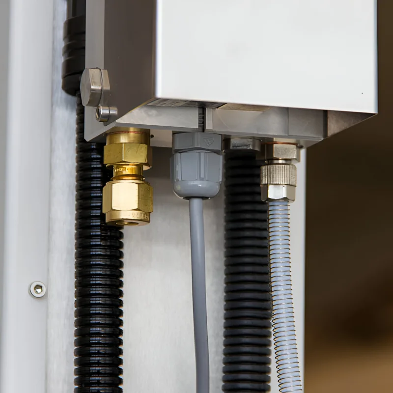
Discover waterproof split cable glands with IP66 IP68 ratings nylon brass stainless steel options ideal for pre-terminated cable installations and retrofitting.
Read More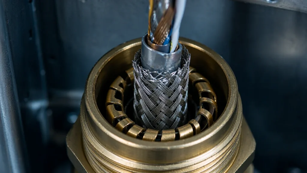
A 360 degree shield termination is a change in the geometry of the return path, not a better earth connection. Transfer impedance, why a pigtail stops working above a few megahertz, and how to verify the bond you made.
Read More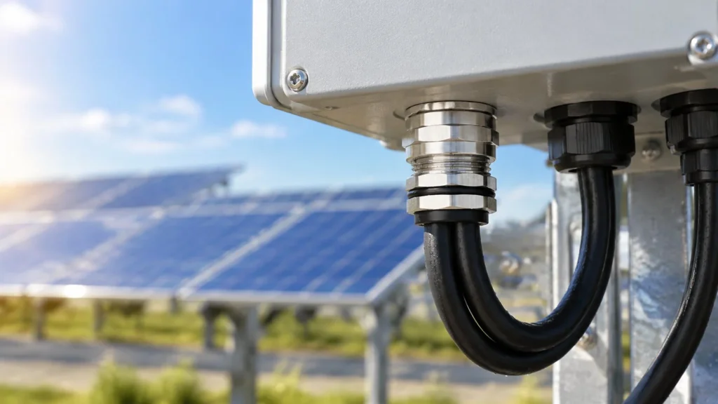
Site class decides more than the datasheet. How UV dose, enclosure wall temperature, IP68 conditions and entry orientation should shape outdoor solar cable gland selection for a 25-year asset.
Read More