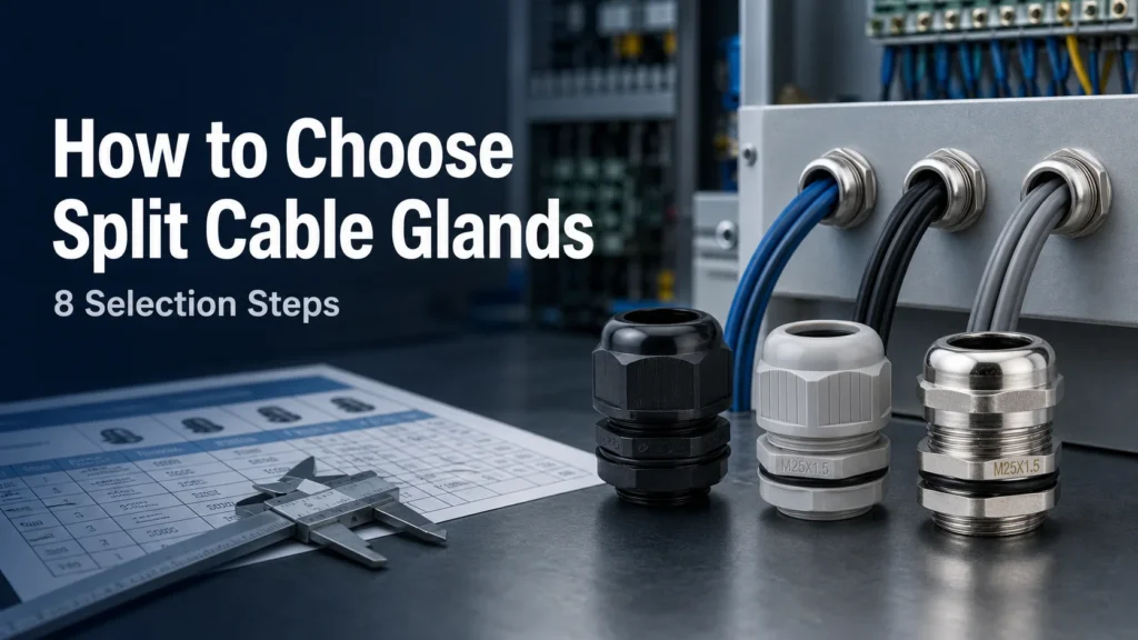
A split кабельный ввод is a clever solution designed to simplify cable entry, especially for pre-terminated cables—those with connectors already attached. Its core design features three main parts:
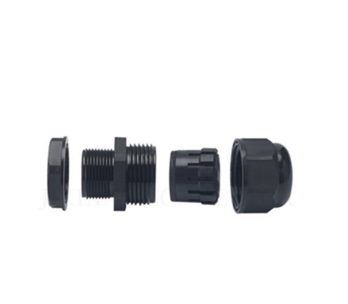
Split body: Two halves that clamp around the cable, allowing easy installation without sliding the gland over the connector.
Pressure screw: Tightens the gland, ensuring a secure and stable grip on the cable.
Sealing inserts: Provide a tight, waterproof seal to protect against dust and moisture.
Easy Assembly for Pre-Terminated Cables
Traditional cable glands require disconnecting and stripping cables, making it difficult or impossible to install on cables with fixed connectors. The split body design of these glands enables you to route cables without removing connectors, saving time and reducing the risk of damage.
Split vs. Standard Cable Glands
Характеристика
Split Cable Gland
Стандартный кабельный ввод
Установка
Installed around pre-terminated cables
Requires sliding over cable ends or connector removal
Assembly
Quick, tool-assisted assembly
Time-consuming; often requires re-termination
Waterproof sealing
IP66/IP68 rated options available
Also available but limited by installation method
Ideal for live systems
Yes—can retrofit without downtime
No—must disconnect cables
Cable condition
Ideal for pre-terminated or fixed cables
Best when the cable end is accessible
Retrofit work
Usually faster and less disruptive
May require disconnection or re-termination
Connector preservation
Connector remains attached
Large connectors may not pass through
Available configurations
Single- or multi-cable inserts, depending on system
Commonly one cable per gland
Cost and simplicity
More components and typically higher unit cost
Often simpler and more economical for new wiring
While standard glands work well for bare cables, their non-split design limits their use with connectors or live cabling. Waterproof split cable glands overcome this by offering reliable sealing and strain relief for complex setups in industrial, marine, and telecom environments.
A split gland is not automatically the better choice. For a new installation with unterminated cable and no expected changes, a conventional gland is simpler and cheaper to buy. The split construction earns its cost when the connector has to stay on.
How Does a Split Cable Gland Work?
A split gland uses a two-part body and a slit elastomer sealing insert. The insert is opened and placed around the cable jacket, then fitted into one half of the body. The two halves close around the insert, and the assembled gland is secured to the enclosure by a thread and locknut, a threaded hole, screws, or a snap-in mechanism, depending on the design.
As the parts close and the pressure screw is tightened, the insert compresses around the cable jacket. That compression does three jobs at once:
Уплотнение — closes the space around the cable to limit the entry of dust and water.
Retention — prevents the cable from moving at the enclosure entry.
Strain relief — reduces the transfer of pulling forces to internal terminals and connectors.
What the assembly actually delivers depends on the whole stack — not on the word “split”. Cable outside diameter, insert size, enclosure surface condition, mounting-hole dimensions, gasket condition, tightening torque and product certification all have to line up. That is the reason the size and torque tables below quote a panel cut-out tolerance as well as a clamping range.
When Should You Use a Split Cable Gland?
Use a split cable gland whenever preserving the cable termination matters more than using the simplest possible entry fitting. Typical situations:
Routing sensor cables with moulded M8 or M12 connectors into control cabinets.
Installing Ethernet, USB, HDMI, D-sub or other connectorised leads.
Bringing complete wiring harnesses into machinery.
Retrofitting a sealed enclosure without cutting and re-terminating cables.
Replacing an entry fitting where the cable cannot easily be disconnected.
Routing several cables through a compatible multi-hole insert.
Passing pneumatic lines, hoses or conduits where the gland manufacturer supports that use.
If none of those apply — new build, bare cable, no expected changes — a standard gland is the more economical answer. Our cable gland application areas page covers the wider picture of where each type is specified.
Why Choose Waterproof Split Cable Glands?
Waterproof split cable glands are a smart choice when you need reliable sealing without the hassle of disconnecting your cables. Here’s why they stand out:
High Ingress Protection: Rated IP66/IP68, these cable glands block dust, dirt, and water even under tough conditions. That means your connections stay safe whether indoors or outdoors.
Strong Strain Relief: They protect cables from pulling or bending forces, reducing the risk of damage or disconnection.
Dust & Moisture Resistance: Essential in harsh environments like marine, industrial, or outdoor setups, keeping your system clean and dry.
Time-Saving Retrofitting: You can route pre-terminated cables without removing connectors, saving hours on installation or maintenance — perfect for live systems.
Preserves Cable Warranty: Since you don’t have to cut or disturb cables, warranties remain valid, and system downtime is minimized.
Ideal for Harsh Environments: Whether it’s saltwater exposure on boats or dust-heavy industrial plants, waterproof split cable glands provide durable, lasting protection.
Choosing waterproof split cable glands helps you keep your projects running smoothly with less risk and downtime.
What Are the Limitations of Split Cable Glands?
The separable construction introduces more sealing interfaces than a one-piece gland, so correct assembly matters more, not less. Compared with an established standard-gland range, split glands also tend to cost more, need a larger mounting footprint, and offer fewer material and certification options.
Check carefully before you specify a split gland for hazardous locations, fire-critical systems, high-pressure washdown, continuous immersion, extreme temperatures, aggressive chemicals, or EMC-sensitive installations. A standard split product does not automatically provide explosion protection, chemical resistance, or 360° shield termination. Each of those requirements has to appear in the manufacturer’s documented specification for the exact model — if it is not in writing, treat it as absent.
GHX Split Cable Glands: A Parameter-by-Parameter Comparison
Most split gland datasheets read the same, so it is worth knowing which numbers actually separate a gland that still seals in year five from one that weeps at the first maintenance. Below is what we measure — on our own production and on competing split glands that customers send us to benchmark against.
What we measure
What we typically find on benchmark samples
GHX split cable gland
How we test it
Sealing insert compound
NBR (nitrile) — cheaper, good oil resistance, poor UV and ozone ageing
EPDM, 70 ± 5 Shore A
Shore A durometer plus 1,000 h UV / ozone exposure, then seal check
Insert compression set
30–38 % after 24 h at 70 °C — the insert stops springing back
18–22 % after the same test
Compression set rig, 70 °C / 24 h, measured to ISO 815
Insert design
Single slit, single lip; a knife-cut seam is common
Moulded single-plane slit with an interlocking double lip
30 open-and-close cycles, then a full immersion test
Body polymer
PA66, frequently with no UV stabiliser declared
PA66 with UV stabiliser, UL94-V0 available
500 h QUV exposure, then impact test at −20 °C
Panel sealing washer
Flat fibre or PVC washer, or none
EPDM profiled washer on a nickel-plated shoulder
Leak check with a deliberately scored enclosure face
Thread tolerance
Stated nominal only; no gauge data supplied
6g tolerance, plug-gauged every production batch
Go / No-Go gauge, in-process, 100 % of batches
IP declaration
“IP68”, with no depth and no duration stated
IP68 stated as 2 m / 24 h; IP66 for split inserts on large sizes
Third-party immersion report, supplied per batch
Salt-spray performance
Usually not stated
96 h on plated brass, 500 h on 316L stainless steel
Neutral salt spray to ASTM B117
Why EPDM and not NBR. Nitrile is the default for low-cost split glands because it is cheap and resists oil well. But a split gland’s insert sits in a longitudinal seam that is under permanent compression, and NBR takes a compression set — the NBR inserts we have measured from benchmark samples came back at 30–38 % permanent set after 24 h at 70 °C, against 18–22 % for our EPDM. Past roughly 25 % the insert no longer springs back after the pressure screw is loosened for maintenance, and the gland weeps the next time it is tightened. EPDM also holds up far better against UV and ozone, which matters because the insert is the one part of the gland that gets exposed every time someone opens it. The trade-off is oil resistance: for gearbox and hydraulic areas we still mould NBR inserts on request.
The other detail we refuse to compromise on is the seam. A split insert has to be moulded and then cut in a single plane — if it is slit twice, or cut with a hot blade that re-welds the edges, the two faces no longer mate cleanly and no amount of torque will close the gap. Every insert we ship is a single-plane moulded cut, and the tolerance on the mating faces is checked as part of the batch inspection rather than at final assembly.
For demanding installations, our heavy-duty stainless steel PG16 gland carries the same insert design in a 316L body, and nylon models cover the cost-sensitive end of the range without dropping the EPDM insert.
Factory-Tested IP68 Data
The IP ratings on this page are the ratings we test to, not the ones we hope for. Every batch is checked on our own immersion bench, and any assembly carrying an IP68 declaration ships with a third-party immersion report. The results below are sample-based and only hold when the cable OD sits inside the insert’s clamping range, the panel cut-out is inside tolerance, and the assembly is torqued to the values in the torque table.
Test
Standard basis
Test condition
Sample
Result
IP68 static immersion
IEC 60529
2 m depth, 24 h
PA66 split gland M20, single-cable insert, cable OD 6–12 mm
Pass — no water ingress
IP68 static immersion
IEC 60529
2 m depth, 24 h
Nickel-plated brass PG13.5, cable OD 6–12 mm
Pass — no water ingress
IP68 static immersion
IEC 60529
2 m depth, 24 h
316L stainless steel M25, double-lip insert, cable OD 13–18 mm
Pass — no water ingress
IP68 after repeated opening
IEC 60529
Insert seam opened and re-closed 30 times, then 2 m / 24 h
EPDM single-plane moulded insert
Pass — seam faces still mate
IP66 water jet
IEC 60529
100 kPa, 12.5 L/min, 3 m distance
PA66 PG29 split insert, cable OD 18–25 mm
Pass — large sizes are declared IP66 as standard
IP69K high-pressure washdown
ISO 20653
80 °C water, 100 bar, 4 positions
316L stainless steel gland, double-lip insert
Pass
Neutral salt spray
ASTM B117
96 h
Nickel-plated brass body, assembled
Pass — no white rust
Neutral salt spray
ASTM B117
500 h
316L stainless steel body, assembled
Pass — no pitting
Two things decide whether you actually get IP68 in service. First, the insert must match the cable: an M20 insert that seals 6–12 mm will pass at 10 mm and fail at 5 mm, because the seam never reaches full compression. Second, the panel cut-out tolerance is plus-only (+0.2 / 0) — a hole punched 0.3 mm oversize lifts the sealing washer off the rim and the assembly loses its rating even though every individual component is correct. Both of those failures look identical to a customer: a gland that passed a bench test and weeps in year two.
Key Features to Look For in Waterproof Split Cable Glands
When choosing a waterproof split cable gland, certain features are essential to ensure reliable performance and durability. Here’s a simple breakdown:
IP Ratings: IP66 vs. IP68
Рейтинг
Уровень защиты
Типичный пример использования
IP66
Dust-tight, powerful water jets
Outdoor equipment, moderate wet environments
IP68
Dust-tight, continuous submersion
Marine, offshore, heavy industrial setups
The IP rating tells you how well the gland resists dust and water, with IP68 offering the highest sealing for toughest conditions.
Materials Breakdown
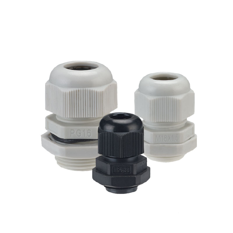
Nylon: Cost-effective, UV-resistant, ideal for general outdoor use.
Brass: Durable and corrosion-resistant, often used in marine or harsh industrial settings.
Нержавеющая сталь: Heavy-duty, excellent for extreme environments needing maximum strength and corrosion resistance. Check out options like the stainless steel cable gland with metric thread for top-tier protection.
Thread Types
Metric (M20 to M63): Most common, suitable for global industrial applications.
PG: Popular in European markets, compatible with older equipment.
NPT: Used mainly in North America for standard pipe thread systems.
A sizing trap worth knowing before you drill: PG13.5 and M20 are often treated as interchangeable, but the cut-outs are not the same — 20.4 mm against 20.0 mm. A PG13.5 gland dropped into a 20.0 mm punched hole still threads, but the sealing washer never reaches full compression around the rim and the assembly will not hold its IP rating. The same applies in reverse for M20 in a 20.4 mm hole. Punch to the thread you actually ordered, and keep the tolerance on the plus side only (+0.2 / 0).
Clamping Range and Multi-Cable Support
Look for glands with a wide clamping range to fit varying cable sizes, plus multi-hole inserts for sealing several cables in one unit. This helps reduce clutter and improve strain relief according to EN 62444 standards.
Our nylon split gland taken apart: locknut, split two-part body, split sealing insert and pressure screw — the cable is fitted with the gland open, so a pre-terminated connector never has to come off.
The two tables below are the numbers we build to. Panel cut-out is the hole you punch or drill; clamping range is the cable outer diameter the insert will actually seal. Read both before you order — most sizing mistakes come from quoting the thread size and assuming the cut-out.
PG thread series
Нить
Panel cut-out Ø (mm)
Clamping range — cable OD (mm)
IP rating as supplied
Max panel thickness (mm)
PG7
12.5 +0.2 / 0
3-6.5
IP68 (2 m / 24 h)
5
PG9
15.2 +0.2 / 0
4-8
IP68 (2 m / 24 h)
5
PG11
18.6 +0.2 / 0
5–10
IP68 (2 m / 24 h)
6
PG13.5
20.4 +0.2 / 0
6-12
IP68 (2 m / 24 h)
6
PG16
22.5 +0.2 / 0
10–14
IP68 (2 m / 24 h)
6
PG21
28.3 +0.2 / 0
13–18
IP68 (2 m / 24 h)
8
PG29
37.0 +0.2 / 0
18–25
IP66 standard / IP68 on request
8
PG36
47.0 +0.2 / 0
22–32
IP66 standard / IP68 on request
8
PG42
54.0 +0.2 / 0
30–38
IP66 standard / IP68 on request
10
PG48
59.3 +0.2 / 0
34-44
IP66 standard / IP68 on request
10
PG63
72.0 +0.2 / 0
42–54
IP66
10
Metric thread series (M × 1.5)
Нить
Panel cut-out Ø (mm)
Clamping range — cable OD (mm)
IP rating as supplied
Max panel thickness (mm)
M12 × 1.5
12.0 +0.2 / 0
3-6.5
IP68 (2 m / 24 h)
5
M16 × 1.5
16.0 +0.2 / 0
4-8
IP68 (2 m / 24 h)
5
M18 × 1.5
18.0 +0.2 / 0
5–10
IP68 (2 m / 24 h)
6
M20 × 1.5
20.0 +0.2 / 0
6-12
IP68 (2 m / 24 h)
6
M22 × 1.5
22.0 +0.2 / 0
10–14
IP68 (2 m / 24 h)
6
M25 × 1.5
25.0 +0.2 / 0
13–18
IP68 (2 m / 24 h)
8
M32 × 1.5
32.0 +0.2 / 0
18–25
IP66 standard / IP68 on request
8
M40 × 1.5
40.0 +0.2 / 0
22–32
IP66 standard / IP68 on request
8
M50 × 1.5
50.0 +0.2 / 0
30–38
IP66 standard / IP68 on request
10
M63 × 1.5
63.0 +0.2 / 0
34-44
IP66
10
All sizes are produced in UV-stabilised polyamide PA66, nickel-plated brass and stainless steel 304/316L; PG63 is available in PA66 and nickel-plated brass. The clamping range is quoted for the standard single-cable insert — for multi-hole inserts the range is split across the number of bores. A split insert carries a longitudinal seam, which is why the larger sizes are declared IP66 as standard: IP68 is supplied with the double-lip insert and declared with its depth and duration in writing (2 m / 24 h unless we agree otherwise), exactly as described in our guide to how IP ratings are actually tested.
Additional Options
EMC Shielding: Provides electromagnetic interference protection, useful in sensitive electronics.
Flame-Retardant (UL94-V0): Important for safety in combustion-prone environments.
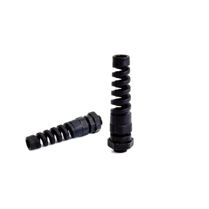
Angled Entries: Offer flexibility in cable routing when straight connections aren’t practical.
Selecting glands with these features ensures you get robust, long-lasting waterproof split cable glands fit for any application.
Split Cable Gland or Split Cable Entry System?
The two terms get used loosely, but the products are not the same. A split cable gland is a compact, gland-shaped fitting installed in a round opening and used for one or a small number of cables. A split cable entry system is a larger rectangular or circular frame carrying several modular inserts.
Choose a split gland for a compact entry with a limited cable count. Move to a modular entry frame when many connectorised cables have to pass through a single cut-out, when the configuration is expected to change often, or when cable density is the main design constraint. Everything on this page applies to the gland; the frame systems use the same sealing principle at a larger scale.
How to Select the Right Waterproof Split Cable Gland
Choosing the right waterproof split cable gland starts with knowing your cable size and setup. First, measure the диаметр кабеля precisely, including any connectors if you’re working with pre-terminated cables. Next, consider the number of cables you need to route—single-hole or multi-cable entry glands have different inserts, so pick accordingly.
Check compatible sizing charts to match your cables and glands properly. For example, nylon glands often cover a wide clamping range but may differ from brass or stainless steel options. Using a reliable cable gland sizing chart helps avoid costly sizing mistakes and ensures a perfect fit without damaging cables.
Think about the environment too: gauge the temperature range, possible chemical exposure, и UV stability requirements for your installation. Harsh outdoor or marine conditions need materials that resist corrosion and wear, so materials like stainless steel or brass might be better than nylon in these cases.
Don’t forget compliance standards. Depending on your industry, your cable gland might have to meet UL, NEMA, RoHS, или EN 45545-2 certifications, especially for rail or marine applications. These standards ensure the gland provides reliable strain relief, waterproofing, and safety.
Work through this checklist against your actual drawing before you request a quotation — it is the difference between a first-pass quote and three rounds of samples:
Measure the cable jacket diameter. Match it to the sealing insert’s stated clamping range. Do not size the insert from conductor area or connector diameter.
Measure the largest connector dimension. Confirm the installation method and available space accommodate the connector and its bend radius.
Count the cables. Decide between a single-cable gland, a multi-hole insert, or a larger split cable-entry frame.
Confirm the mounting interface. Check cut-out diameter, panel thickness, thread standard, locknut clearance, and whether a flat sealing surface is available.
Define ingress protection. Select a tested rating appropriate to dust, rain, water jets, washdown, or immersion — and get the depth and duration in writing.
Check the environment. Review temperature, UV exposure, oil, chemicals, salt spray, vibration and mechanical impact.
Verify material and compliance. Nylon, nickel-plated brass and stainless steel serve different environments. Confirm the approvals your market requires rather than assuming equivalence.
Review strain-relief and EMC needs. If pull-out resistance or cable-shield termination matters, require documented performance for those functions.
Common mistakes to avoid:
Choosing a gland too small, causing cable pinching or damage.
Overlooking connector size, which can block installation.
Ignoring environmental specs, leading to premature failure.
Skipping compliance checks, risking safety and warranty issues.
For more detailed guidance, check out this comprehensive guide on how to choose the right IP rating and select cable glands appropriate for your application needs. This helps ensure you get the best waterproof split cable gland that matches your exact requirements.
Installation Guide for Waterproof Split Cable Glands
Tools and Preparation
Before starting, gather essential tools: an adjustable wrench or spanner, wire strippers, a torque screwdriver, and cleaning cloths. Clean the cable and gland surfaces to remove dust, oil, or debris, ensuring a tight seal. Verify cable diameter and connector type against the gland’s sizing chart for compatibility.
Torque Settings and Panel Cut-out (Our Workshop Data)
Torque is the single number that decides whether a split gland holds its IP rating in service, and it is the number most often left off a datasheet. The values below are the assembly torques we use on our own production line, measured on a calibrated torque wrench on dry threads at 20 °C. Tighten the body into the panel first, then the pressure screw onto the cable — not the other way around.
Нить
Spanner flats (mm)
PA66 body (N·m)
Nickel-plated brass (N·m)
Stainless steel (N·m)
PG7 / M12
15
2.5
5.0
4.0
PG9 / M16
18
3.0
6.0
5.0
PG11 / M18
20
3.5
7.0
5.5
PG13.5 / M20
22
4.0
8.0
6.0
PG16 / M22
24
5.0
10.0
7.0
PG21 / M25
27–30
6.0
12.0
8.0
PG29 / M32
34–40
8.0
15.0
11.0
PG36 / M40
43–50
10.0
18.0
13.0
PG42 / M50
54–57
12.0
22.0
16.0
PG48 / M63
64–68
14.0
25.0
18.0
Panel preparation. Punch or drill to the cut-out in the size tables above, plus 0.2 mm on the diameter and nothing on the minus side. Deburr both faces: a 0.3 mm burr is enough to hold the washer off the panel and create a leak path.
Panel thickness. Minimum 1.5 mm — thinner panels deform at torque and the body works loose. Maximum per size is given in the size tables (5 mm at PG7 up to 10 mm at PG48 and above).
Bare metal under the washer. The EPDM washer must sit on clean, unpainted metal. Powder coat under the washer compresses and relaxes, and paint film on the thread changes the effective torque.
Nylon relaxes. A PA66 body loses roughly 10 % of its clamping load in the first 24 hours. Re-check the torque after the first thermal cycle or after 24 hours in service and bring it back to the table value.
Stainless steel galls. We cap the stainless torque below the brass figure for exactly that reason. Use a nickel anti-seize compound on 316L threads, and never run a stainless nut onto a stainless body dry at high speed.
Do not reuse a deformed insert. If an insert has been left compressed for months, or shows a visible set in the seam faces, replace it — it will not reseal even at the correct torque.
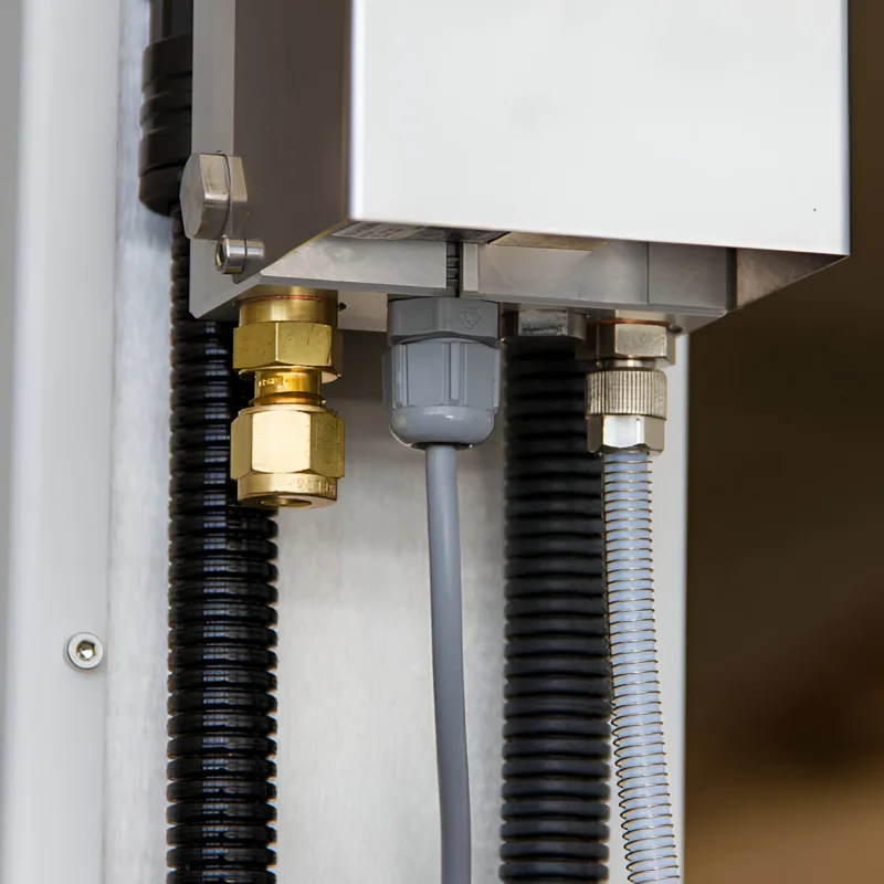
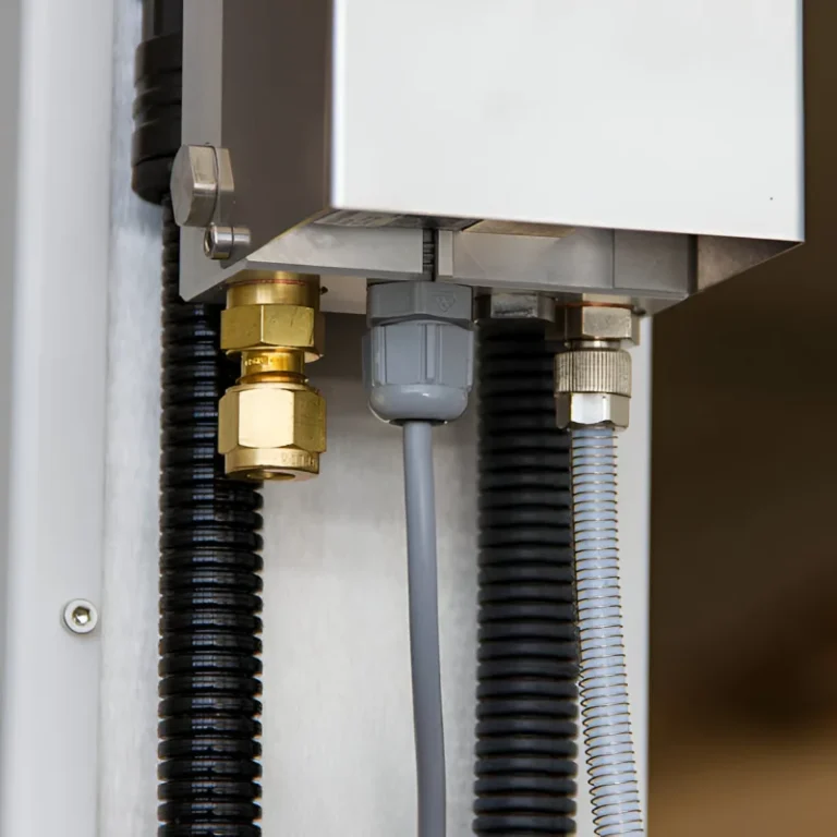
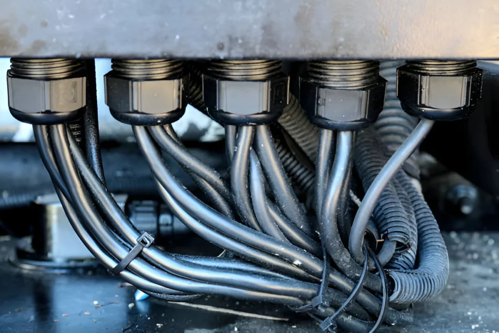
Real installation: nylon and brass glands entering the bottom wall of an enclosure — washer flat on bare metal, insert seam facing down.
Assembly Process for Pre-terminated Cables
Open the body. Separate the two halves and check the insert seam: it should be a single, straight, clean cut with the two faces meeting along its full length. This takes five seconds and catches the most common defect in a split gland.
Fit the body to the panel. Pass the body through the cut-out from outside, run the locknut on from inside, and tighten the body to about 60 % of the table torque — for PG13.5 that is 2.5 N·m in PA66, 5 N·m in brass. The washer must end up flat against bare metal.
Set the cable into the insert. Open the split insert around the cable at the position it will occupy, then close it so the cut faces return to their moulded alignment. Never trim an insert to fit a cable.
Close the body. Bring the two halves together over the insert and start the pressure screw by hand, checking that the insert has not rotated out of the seam.
Torque the pressure screw. Take it to the table value — 4.0 N·m for PG13.5 in PA66, 8.0 N·m in brass. A torque screwdriver is not optional here; the difference between sealing and stripping an insert is about two turns.
Orient and re-check. With the gland horizontal or below, roll the insert so the seam faces down (6 o’clock) — that keeps water from pooling on the cut. After 24 hours or the first thermal cycle, re-check torque; PA66 bodies typically need a small top-up.
Torque and Sealing Best Practices
Stay inside the window. Under-torque leaves an unsealed seam; over-torque deforms the insert permanently and is not recoverable. The window for a PG13.5 brass gland is 8 N·m — at 12 N·m the insert takes a set and the gland will leak on the next re-tightening even if you bring it back to 8.
Compress, do not crush. The EPDM insert should compress by roughly 25–30 % of its wall thickness. When it looks visibly squeezed flat past the nut face, you are over the window.
Match the insert to the cable, not to the gland. Inserts come in diameter steps; picking the step above or below the real cable OD is the most common cause of a gland that passes a bench test and fails in service.
Keep the thread and washer clean. Grit or swarf on the thread costs torque to friction instead of to the seal, so the gland reads correctly on the wrench while being under-tightened on the cable.
Seam down, always. On a horizontal or downward entry, orient the insert cut to 6 o’clock. On an upward entry, add a bead of neutral-cure silicone over the seam as a second line of defence.
Troubleshooting Full IP Rating
Test the gland for leaks after installation, especially in outdoor or marine environments.
Inspect seals for cracks or misalignment.
Re-seat or replace inserts if the gland fails waterproof testing.
Confirm all threads are fully engaged and torque values met to maintain IP66/IP68 protection.
When a gland does fail a leak test, the cause is almost always one of these five — check them in this order before you blame the product:
An insert used outside its stated cable range.
Mounting onto a rough, painted or curved surface instead of flat bare metal.
Debris or swarf trapped in the insert seam or on the washer face.
The enclosure gasket omitted, or a flat fibre washer used in its place.
Over- or under-tightening — both leave the seam unsealed, and over-torque is not recoverable.
Safety Considerations
Always disconnect power before installation to avoid electric shock.
Wear appropriate personal protective equipment (PPE).
Avoid sharp cable bends near the gland to prevent damage.
Follow workplace safety guidelines during installation.
Waterproof split cable glands are perfect for a wide range of industries where reliable sealing and easy installation are critical. In industrial automation and control panels, these glands provide secure routing of pre-terminated cables, helping reduce downtime during maintenance. They deliver strong strain relief and high ingress protection, ensuring equipment runs smoothly in dusty or wet environments.
For marine and offshore installations, the corrosion-resistant options, such as stainless steel or brass waterproof cable glands, handle harsh saltwater and extreme weather conditions. Their IP66/IP68 ratings guarantee cables stay dry, while split designs allow for retrofitting without disrupting live systems, essential for offshore safety.
In the renewable energy sector, including solar and wind power, split cable glands simplify installation and repairs of multi-cable setups within outdoor enclosures. Telecommunications infrastructure also benefits from split cable glands that protect sensitive connections from moisture and dust, ensuring consistent network performance.
Machinery and robotics environments demand robust cable entry solutions that combine strain relief and EMI shielding. Split cable glands fit well into these setups by accommodating shielded or armored cables, simplifying upgrades, and maintaining compliance with industrial standards.
A real-world example: A manufacturing plant upgraded its control panel wiring using waterproof split cable glands to replace damaged glands without disassembling equipment. This reduced downtime significantly while maintaining IP68 protection, demonstrating how split designs solve practical challenges.
Keeping your waterproof split cable gland in top shape ensures long-term reliability and protection. Here’s how to maintain and troubleshoot for sustained waterproofing:
Long-Term Care for Waterproofing
Regular Inspection: Check glands periodically for cracks, corrosion (especially in brass or stainless steel), and seal integrity.
Cleanliness: Remove dirt, dust, and debris that may compromise the seal or strain relief.
Lubrication: Some sealing inserts benefit from light silicone grease to maintain flexibility and prevent drying out.
Signs of Wear and When to Replace
Visible Damage: Cracks, deformation, or discoloration of the gland or seal indicate replacement.
Loss of Tightness: If the gland no longer holds the cable firmly or the pressure screw feels loose despite proper torque.
Water Ingress: Moisture or condensation inside enclosures signals a failure in waterproofing.
Corrosion: For brass or stainless steel glands, signs of rust or pitting mean it’s time for a new gland.
ЧАСТО ЗАДАВАЕМЫЕ ВОПРОСЫ
Can a split cable gland be installed after the connector is attached? Yes — that is its primary purpose. The body and sealing insert open and close around the cable behind the connector, so the connector never has to pass through the gland.
Can I use one gland for multiple cables? Yes. Multi-cable entry glands are available with multi-hole inserts designed for secure sealing and strain relief of several cables. Every cable must fall inside the range for its own bore, and unused openings must be closed with approved blanks.
Are all split cable glands waterproof? No. Protection ratings vary by model and by assembly. Always check the tested IP or NEMA rating together with the conditions attached to it — cable range, insert type, mounting method and enclosure interface.
Are waterproof split cable glands compatible with armored cables? Only when the product documentation explicitly supports that cable construction and the required armour termination. Many split glands seal the outer jacket only and do not provide the mechanical or electrical functions of an armoured cable gland.
Can split cable glands provide EMC shielding? Only models specifically designed and documented for shield termination should be treated as EMC glands. A metal body on its own does not guarantee continuous, low-impedance contact with the cable screen.
How do I maintain the IP68 rating after installation? Tighten to the recommended torque, check that the sealing insert is seated and the seam is not twisted, and re-check torque after the first 24 hours or the first thermal cycle — PA66 bodies typically need a small top-up.
What information should I send a supplier? Cable outside diameter, connector dimensions, cable quantity, enclosure cut-out and panel thickness, required IP rating, material preference, temperature and chemical exposure, thread standard, strain-relief requirements, and any mandatory approvals. With those in hand we can confirm a model, a price and a lead time in one reply.
Key Takeaway
A split cable gland is the practical choice when a terminated cable has to enter an enclosure without cutting off its connector. It combines a separable body and a sealing insert to simplify installation while providing cable retention, strain relief and — when specified and assembled correctly — documented environmental sealing.
Choose it from documented cable range, mounting dimensions, protection rating, environment and compliance requirements rather than from thread size alone. That is also how you avoid the two failures we see most often: an insert sized a step too large, and a panel cut-out punched 0.3 mm oversize.
Изучите прочные водонепроницаемые кабельные сальники с классом защиты IP67 и IP68 из нейлона, латуни и нержавеющей стали для надежной защиты кабеля и снятия напряжения.
A brass waterproof cable gland helps protect cable entries from water, dust, and strain in industrial and marine installations. Learn how to choose the right model, size, and supplier.
Мы используем файлы cookie для улучшения вашего восприятия, предоставления персонализированной рекламы или контента, а также для анализа нашего трафика. Нажав кнопку "Принять все", вы соглашаетесь с использованием нами файлов cookie.