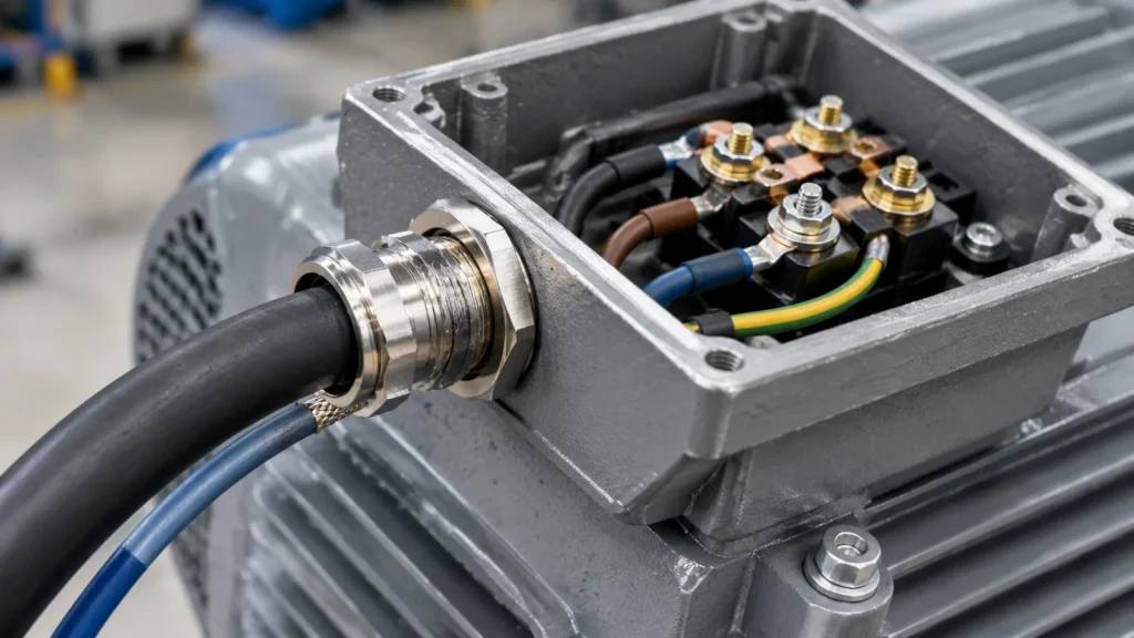
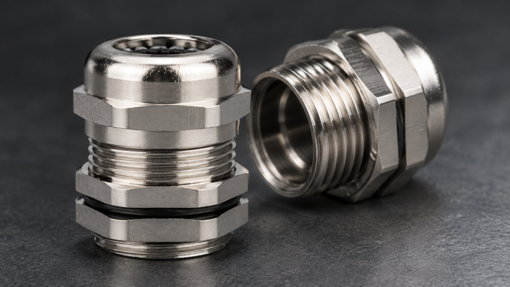
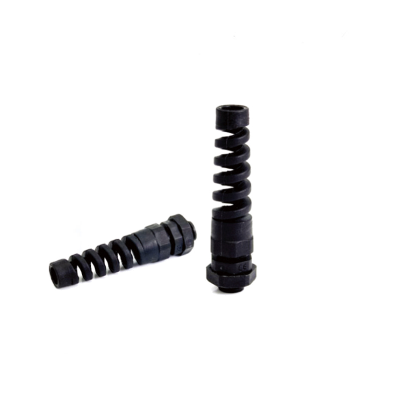
A motor terminal box is the least forgiving cable entry on an industrial site. It is bolted to a vibrating casting, it sits in the thermal plume of a winding that is designed to run hot, its walls are thin cast aluminium with threads that strip before the gland does, and it is frequently covered by the motor manufacturer’s warranty in ways the panel builder never reads.
This guide covers the motor end as a physical interface: what the three common entry configurations give you, why heat and vibration arrive from inside the machine rather than from the room, and where a gland choice crosses into someone else’s warranty. The electrical side of the same joint, including the bond path along the drive cable, is covered in our guide to the VFD cable gland.
The Motor Is Not a Box With a Hole in It
An enclosure is static, is designed around its internals, and is normally accessible. A motor is none of those. The casting is stiff enough to transmit vibration rather than absorb it, the internal volume is fixed by the winding and the terminal studs rather than by the cable, and access is whatever the plant layout left you.
That combination changes what the gland is being asked to do. On a panel, the gland mostly resists water. On a motor, it also has to survive continuous low-amplitude movement, a wall that is often thinner than the thread length assumes, and a temperature that is set by the machine rather than by the weather.
Three Entry Configurations, Three Different Problems
Configuration
What it looks like
The problem it creates
Top-mounted terminal box
Cast box on top of the frame, entries on the sides or underside
Water runs down the conduit into the box; entries must face down
Side-mounted box
Box on the frame flank, close to the shaft end
Restricted wrench access; entries may face the driven equipment
Flying leads, no box
Pigtails emerging through a grommet or plate
No thread to seal against; needs a plate or a proper entry plate conversion
Frame-mounted, integral terminal chamber
Cast chamber with a cover, entries in the casting
Thread is cut into a thin, sometimes reamed wall with limited engagement
In all four cases the entry is decided by the motor manufacturer, not by the panel builder, so the useful question is not which gland you would prefer but which gland the existing thread can hold. Measure the thread, count the engagement depth, and check that the box has room for the gland body inside the cover.
Vibration Comes From the Rotor, Not the Room
A motor generates its own excitation at twice line frequency from the magnetic circuit, plus whatever the bearings and the driven load contribute. That is continuous, present from the first start, and it is transmitted directly into the casting the gland is screwed into. A gland on a static panel next to the same motor sees a fraction of it.
The consequence is that motor entries belong at the top of the inspection priority, not the bottom. Threaded joints loosen by transverse motion, and a casting bolted to a rotor delivers exactly that. Clamp the cable so the gland is not the last restraint, and expect to re-check the body torque after the first weeks of running rather than after a year. Our guide to preventing cable glands from loosening sets out which hardware actually addresses this and which does not.
Cast Aluminium Threads Are the Weakest Joint on the Machine
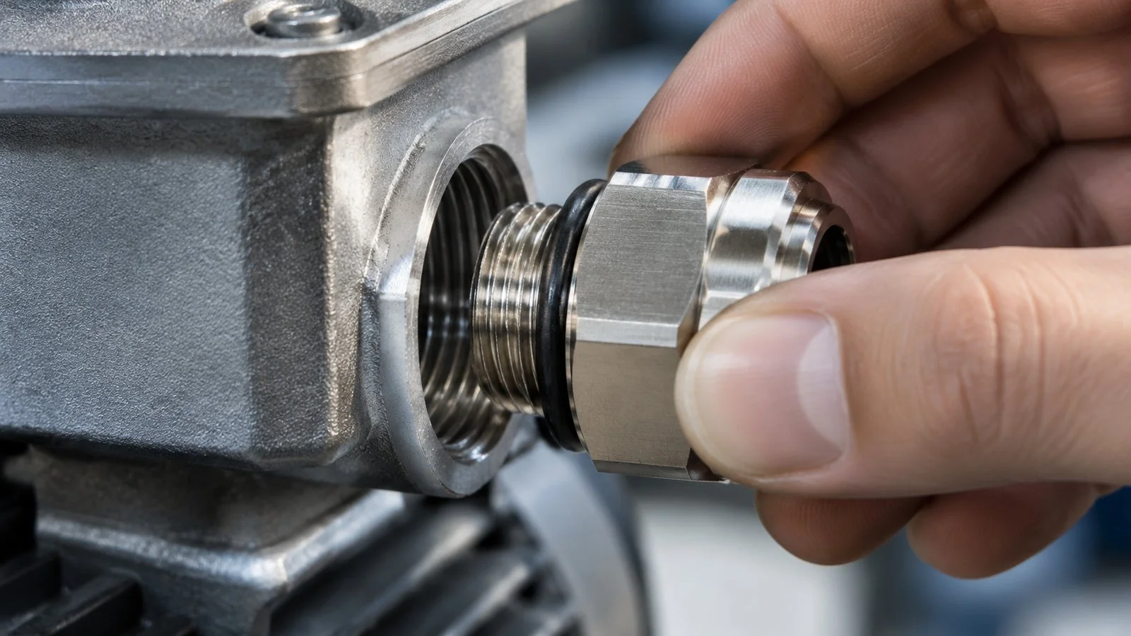
An aluminium casting has a much lower tolerance for repeated tightening than a brass gland, and the thread in the box is usually the part that fails first. Two things follow. First, the torque that matters is the casting’s limit, not the gland’s, so a value taken from the gland datasheet may already be too high for the box. Second, a cross-threaded entry on a motor is not a nuisance, it is a repair that requires a thread insert or a new cover.
Start the thread by hand and confirm several full turns before a tool touches the casting.
Practical discipline: start the thread by hand and confirm at least several full turns before any tool is used, use a washer or locknut to spread the bearing load on thin walls, and never chase a leak by adding torque to an aluminium thread. If the casting is already damaged, a thread repair insert is the correct fix and should be done before the gland is fitted, not after a second leak.
Heat Arrives From the Winding, Not the Air
The terminal box sits in the thermal plume of a machine whose whole purpose is to convert electrical energy into heat and torque. Box internal temperature therefore tracks winding temperature far more closely than it tracks ambient, and the cable inside the box is the hottest part of the whole run. That is the temperature the gland seal actually experiences, and it is routinely higher than the ambient figure on the project datasheet.
This is where the material window becomes a real constraint rather than a specification formality. Plated brass and stainless tolerate far more than nylon, and the seal is the first component to give up regardless of body material. Our guide to high temperature cable glands covers the material pairing in detail; the motor-specific point is simply that the measurement has to be taken at the box, not in the aisle.
Power and Feedback Need Separate Entries
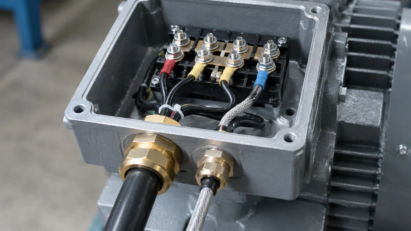
A modern motor usually brings more than one cable. Power enters at one size, and an encoder, a thermistor or a PTC string enters at another, often with a much smaller cross-section and a very different shielding requirement. Running both through one entry, or through two entries drilled wherever space allowed, is the origin of most feedback faults on site.
One thick power cable and one screened feedback cable, each through its own gland at its own size.
Separate entries are the correct arrangement for three reasons: the gland sizes are different and a shared multi-hole insert compromises both seals; the feedback cable needs its own shield termination rather than being bonded to the power screen; and maintenance on one cable should not disturb the other. Where the feedback pair is screened, the termination geometry matters more than the gland itself, and our guide to 360 degree shield termination covers the joint at the motor end, with the matching EMC gland with 360 degree contact as the reference part.
Internal Clearance Sets the Gland Length
The gland projects into the box as well as out of it, and on a motor the inside is the tighter side. The dome nut and the cable’s bend have to fit between the entry and the terminal studs without touching the winding leads, and the minimum bend radius of a thick power cable is not small. The result is that a standard thread length can be the wrong choice even when the thread is correct, because the body sits too far into the chamber.
Two solutions exist and they are not interchangeable:
Option
What it solves
What it costs
Longer thread
Moves the body outward, gaining room between the entry and the terminals
Extra length outside the box; check the cover still closes
Elbow or right-angle entry
Redirects the cable immediately, where there is no room to move outward
Adds a bend at the first point of entry; harder to pull through
Entry plate or adapter
Relocates the entry on a casting that cannot be altered
Adds a joint, and a seal that has to be specified with it
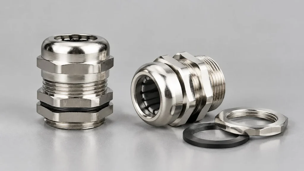
Choosing between them is a measurement, not a preference: measure from the inner face of the entry to the nearest obstruction before ordering, and check that a cable bent at that point still respects its minimum radius. The longer thread nylon gland exists for exactly the first row of that table, and the elbow version for the second.
Washdown, Weather and the Motor’s Own IP Rating
A motor rated IP55 in a washdown area is not a motor that needs a better gland; it is a motor that will fail regardless of the gland, because the frame and the fan cover are the leak path. The gland can only be as good as the enclosure it enters, and on motors the enclosure rating is the manufacturer’s claim, not yours.
Where the motor is genuinely rated for the environment, the gland should match it and no more. An IP68 gland on an IP66 motor adds cost without adding protection, and it can add a problem: a fully sealed entry on a box that breathes through its own seals can trap condensation against the terminals. Our guide to IP rating selection explains where the extra rating buys something and where it does not.
Specifying the Motor Entry Without Crossing the Warranty Line
Field
What to write
Why
Box thread
Measured, including pitch; metric or PG
Motor makers use both, sometimes on one machine
Engagement depth
Available thread length in the casting
Sets whether a standard or long thread is required
Internal clearance
Entry face to nearest obstruction
Decides straight or elbow entry
Box temperature
Measured at the box, at operating load
The number that picks material and seal
Entries required
One power, one feedback or thermistor
Separate sizes and separate shield treatment
Approval
Written confirmation from the motor maker
Drilling or enlarging an entry can void it
The last line is the one that gets skipped. Enlarging a knockout, adding an entry, or fitting a heavier gland than the casting was designed for can all be treated as a modification by the motor manufacturer, and the conversation after a failure is much more expensive than the email before installation. Keep the entry schedule as a document that the motor supplier has seen, and the boundary stops being a grey area.
For the enclosure side of the same problem, including wall materials and gland plate practice, see the enclosure entry guide; the principles transfer directly to a motor terminal chamber.
Questions fréquemment posées
What cable gland should I use for a motor?
Match three things: the thread actually cut into the terminal box, the measured cable sheath diameter, and the temperature measured at the box rather than at the wall. Material follows the temperature; the brass and stainless families cover the hot cases.
Can I run power and encoder cables through one gland?
Not good practice. The sizes differ, the shield treatment differs, and a shared insert compromises both seals. Separate entries also let one cable be serviced without disturbing the other.
Why do motor glands come loose more often than panel glands?
Because the casting is bolted to a rotor and delivers continuous transverse motion at the thread. Support the cable so the gland is not the last restraint, and re-check torque after the first weeks of running.
Can I drill an extra entry in a motor terminal box?
Only with the motor manufacturer’s written approval. An added or enlarged entry can be treated as a modification and can void the warranty, and the casting may not have material where you intend to cut.
Does a VFD change the gland requirement?
It changes the bonding requirement, not usually the mechanical one. A drive output needs a proper screen termination at both ends, which is a shield path problem rather than a thread or seal problem.
M25 is the size people arrive at after an M20 range failure. This guide gives the published dimensions, the 25 to 25.2 mm hole, and the four sizes that share the same 10 to 14 mm cable band.
PG and metric cable glands are separate thread systems, not two names for one fitting. Flank angles, the nearest-size table, why PG13.5 will not enter an M20 hole, and when an adapter is the right answer.
Si vous protégez des câbles, vous savez à quel point un bon presse-étoupe étanche est crucial. Les presse-étoupes sont les héros méconnus qui protègent votre câblage de l'eau, de la poussière et des dommages mécaniques. En particulier dans les environnements industriels difficiles, le choix du bon type de presse-étoupe peut faire ou défaire votre [...]
Nous répondrons à votre demande dans les 24 heures
Nous accordons de l'importance à votre vie privée
Nous utilisons des cookies pour améliorer votre expérience de navigation, vous proposer des publicités ou des contenus personnalisés et analyser notre trafic. En cliquant sur "Tout accepter", vous consentez à notre utilisation des cookies.