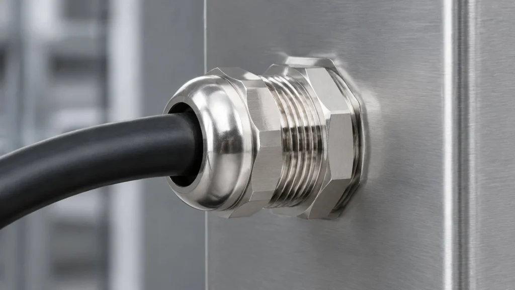
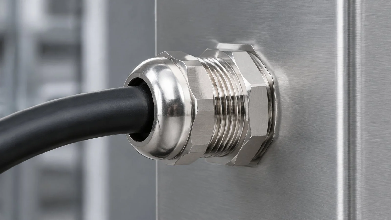
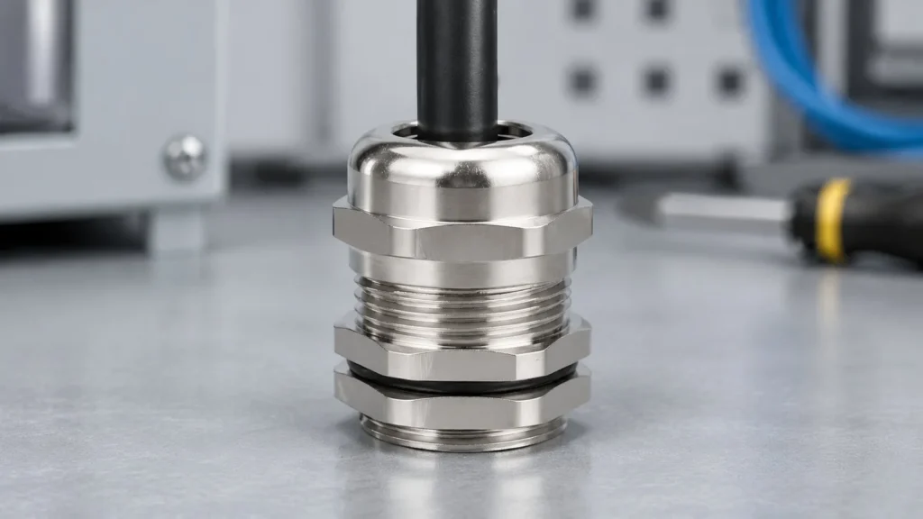
A 1/2 inch NPT cable gland is the most mis-ordered entry size in the catalogue, and the reason is in the name. The half inch is a nominal pipe size: it was never the thread diameter and it is not the hole. The thread measures 21.34 mm across its large end, 1.34 mm more than an M20 and 0.66 mm less than an M22 — close enough to both that fitters try, and far enough that neither works. Standard values below come from ASME B1.20.1; the rest from this site’s M and PG tables.
A 1/2 inch NPT entry seals on its thread, not at the face. That one fact explains why the hole, the locknut and the sealant all behave differently from a metric entry.
What the “1/2” Actually Measures
The number is inherited. NPT sizes descend from iron pipe practice, where the nominal figure referred to a bore and the thread was cut outside it. A thread outside a bore must be larger than the bore, so every size sits one step above its name: half inch pipe carried a bore near 12 mm and a thread a little over 21 mm.
NPT size
Thread O.D. at large end
Threads per inch
Pitch
1/4 inch
13.72 mm
18
1.41 mm
3/8 inch
17.15 mm
18
1.41 mm
1/2 inch
21.34 mm
14
1.81 mm
3/4 inch
26.67 mm
14
1.81 mm
1 inch
33.40 mm
11.5
2.21 mm
The Diameter Only Exists at One Plane
No single diameter describes a tapered thread. On NPT the flank closes at 1 in 16 on diameter, so across a 15 mm thread the outside diameter shrinks by about 0.94 mm from large end to small end. That is a third of the entire gap between an M20 and an M22, produced by sliding a caliper along one component.
A measurement is only comparable when taken at the same place twice, and on NPT that place is set by hand-tight engagement, not by wherever the jaws land. Measured at the nose, a 1/2 inch thread reads about half a millimetre under 21.34 mm, and a hole ordered from that number will not start. Metric work has no such failure: a straight thread is one diameter throughout.
The Hole a 1/2 Inch NPT Entry Needs
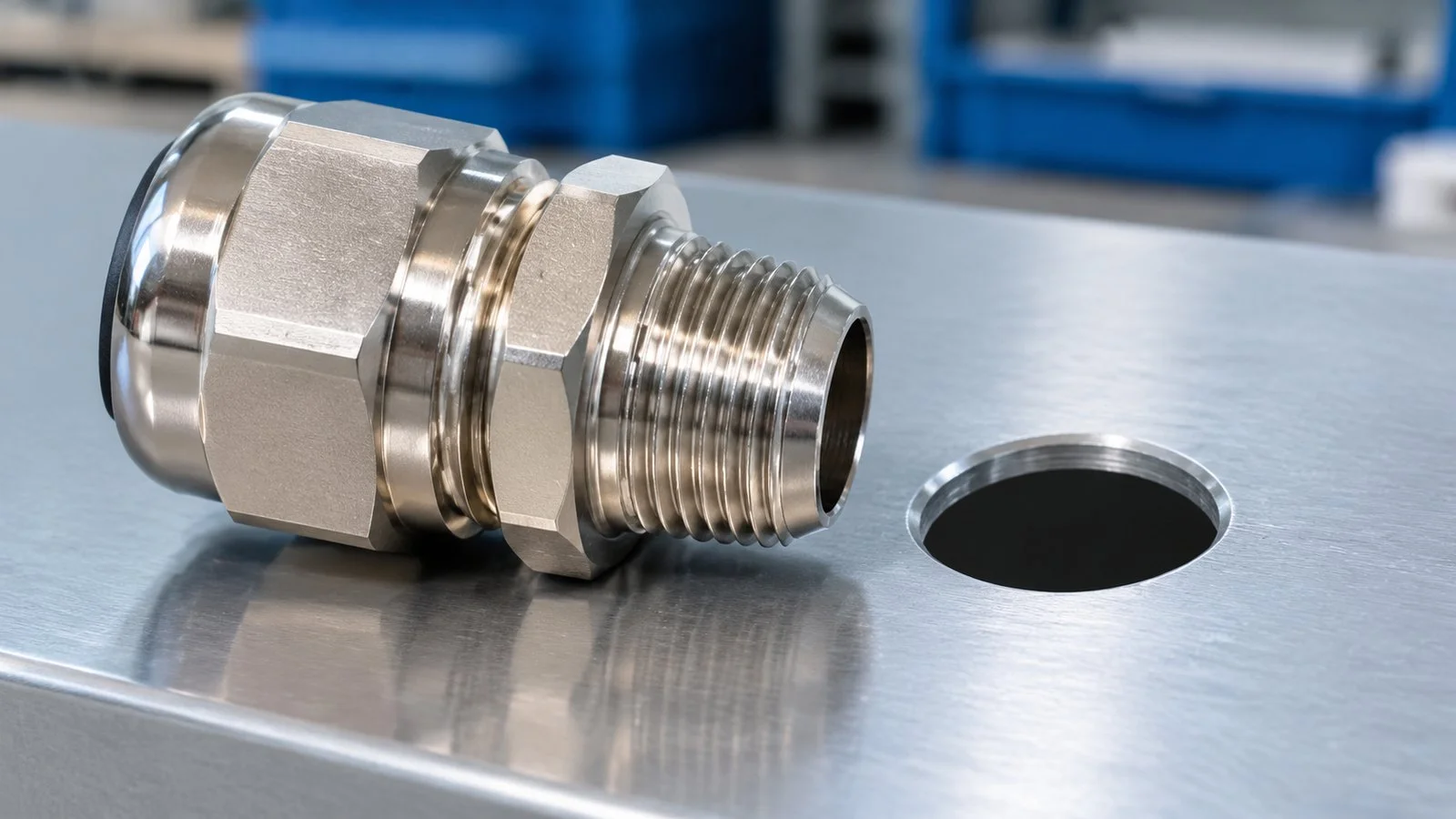
An NPT entry accepts two hole preparations, which are not variants of one another. The first is a tapped and reamed tapered hole cut with a 1/2-14 NPT tap to the depth that brings the thread to its gauge plane. The second is a plain clearance hole with a locknut behind the wall, for sheet too thin to contain a taper.
Preparation
Hole
Wall needed
What seals it
How it fails
Tapped and reamed
1/2-14 NPT tap, full depth
Thick enough for full engagement
Thread flanks plus sealant
Tap stops short, gland engages three or four turns
Clearance plus locknut
21.5 mm or larger
Thin sheet
Washer at the face
No straight section for the locknut to bear on
The clearance figure is the one written down wrongly. A clearance hole must clear the large end, so it starts at 21.5 mm, not at the 20.2 mm carried over from M20 work because both entries sound “about 20”. A 20.2 mm hole will not take a 21.34 mm thread: the gland sits on the face like a cap.
Turned around, the error is quieter and worse. An M20 gland drops into a tapped 1/2 inch NPT hole and turns two or three times before the taper closes on it, which feels like a fit and leaks on the first wet day. Both directions are common on mixed panels; the full relationship is in this hole size chart.
The thread and the hole are two different numbers: 21.34 mm for the thread, 21.5 mm and up for the clearance hole.
Why a 1/2 Inch NPT Gland Has No Cable Range
The thread never touches the cable. The cable is gripped by an insert inside the body, and the insert sets the range on the datasheet. Two suppliers can ship the same 1/2 inch NPT gland with ranges four millimetres apart, because they put different bodies behind the same thread: the thread decides the panel, the insert decides the cable.
Equivalent body
Cable range
Filet O.D.
Mounting hole
Thread length GL
Spanner
M20
6 mm to 12 mm
20 mm
20 mm to 20.2 mm
8 mm
22 mm
PG13.5
6 mm to 12 mm
20.4 mm
20.4 mm to 20.6 mm
8 mm
22 mm
M22
10 mm to 14 mm
22 mm
22 mm to 22.2 mm
8 mm
24 mm
PG16
10 mm to 14 mm
22.5 mm
22.5 mm to 22.7 mm
9 mm
24 mm
Which of those bands a 1/2 inch NPT entry delivers depends on the insert behind it, which is why “what cable does a 1/2 inch NPT gland take” has no standard answer: the reply has to be a range plus a hole, not a size. The M20 brass body and the PG13.5 equivalent show the two bands side by side on the same 20 mm class of entry.
1.34 mm From M20 and 0.66 mm From M22
Entry
Filet O.D.
Mounting hole
Difference from 1/2 inch NPT
1/2 inch NPT
21.34 mm
Tapped, or 21.5 mm clearance
—
M20
20 mm
20 mm to 20.2 mm
1.34 mm smaller
PG13.5
20.4 mm
20.4 mm to 20.6 mm
0.94 mm smaller
M22
22 mm
22 mm to 22.2 mm
0.66 mm larger
PG16
22.5 mm
22.5 mm to 22.7 mm
1.16 mm larger
The closest number is M22 at two thirds of a millimetre, which sounds like a margin and is not one. A 1/2 inch NPT thread advances 1.81 mm per turn and an M22 advances 1.5 mm, so the pair never tracks: it binds on the second turn and a fitter who keeps turning cuts a new thread in the softer part. Whether substitution can ever be defended also depends on where each system seals, the subject of this NPT and metric comparison.
Engagement Depth Sets the Minimum Wall
ASME B1.20.1 defines a hand-tight engagement length for every NPT size, and for 1/2 inch it is 0.53 inch: about 13.6 mm, or roughly seven and a half turns of a 14 TPI thread. That is not a torque value. It is the distance the thread must travel before the joint reaches its gauge plane, and it sets the wall a tapped entry requires.
Seven and a half turns cannot be cut into a 3 mm sheet: there is not enough material to contain the taper, so at the small end no full flanks are left and the joint holds almost nothing. That is where a clearance hole and a locknut is correct — and also where the locknut needs a straight section to bear on, which a fully tapered gland does not provide. On a thin wall the workable answers are an adapter to a straight thread or a different entry, not a locknut forced onto a taper.
Three Ways the Joint Fails on Site
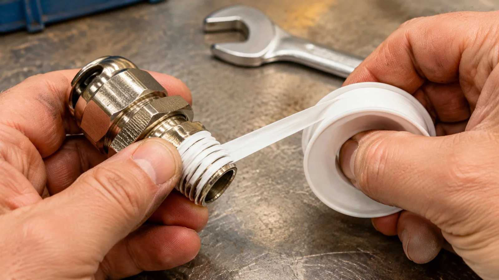
Dry threads. An NPT joint with clean, dry threads leaks at the flank. Sealant is part of the sealing system here, not an accessory — the exact opposite of the metric rule, where tape on the thread is a defect.
Too much tape. Four or five wraps stop loading the thread and start loading the enclosure boss; on a cast boss the ear can crack, on a welded boss the weld takes the load. Two or three wraps in the direction of the helix, first thread bare, seals the joint without preloading the wall.
Chasing the wrong leak. Water appears at the entry, so the fitter adds tape and torque. The path was the insert six millimetres further out. A taper also starts loosely by hand, which reads as correct alignment: a gland can begin cross-threaded and only bind on the third turn.
Sealant on the thread is correct for NPT and wrong for metric. Two or three wraps in the direction of the helix, first thread bare.
Material, Temperature and What the Thread Does Not Cover
A thread callout specifies a thread, not ingress protection, temperature or corrosion; those come from the body and the seal. A gland described only as “1/2 inch NPT” is a third of a specification, and an NPT thread on a stainless body behaves very differently on a coastal plant.
IP68 is where this bites hardest, because IP68 is a placeholder rather than a number: the rating means nothing until a depth and a duration are attached. The graded positions used on this site are 1.5 m for 30 minutes, 2 m for 24 hours as the standard claim, 5 m for 72 hours for marine and tunnel work, and 10 m for 168 hours on request. A gland quoted as “IP68” without one of those pairs is an unverified claim.
Temperature ceilings follow the body: PA66 nylon −40 °C to +100 °C, brass −40 °C to +120 °C, SS304 or SS316L −40 °C to +200 °C. North American hazardous locations expect an NPT entry; the EU equivalent is ATEX or IECEx on an M or PG entry, so a project spanning both needs two part numbers, not one adapter.
A Purchase Checklist for 1/2 Inch NPT Glands
The catalogue on this site is built on M and PG threads, and a 1/2 inch NPT requirement is quoted as a thread option rather than picked off a shelf. That makes the content of the enquiry matter more, not less. The metric and PG dimension sets themselves are in this thread size chart.
Item
What to state
Why it changes the part
Fil
1/2-14 NPT, taper to ASME B1.20.1
Stops 1/2 inch BSP being supplied; BSP is 20.96 mm at 14 TPI with a 55° flank
Hole preparation
Tapped, or clearance plus locknut
Decides whether a straight section is needed behind the taper
Wall thickness
Millimetres at the entry
Sets whether a tapped entry is possible at all
Cable O.D.
Measured, not nominal
Sets the insert and therefore the cable range
Insert material
EPDM, silicone or nitrile
Temperature and chemical compatibility
Ingress protection
Depth and duration, not just IP68
Turns the rating into something a test report can confirm
Body material
Nickel-plated brass, SS304 or SS316L
Sets the temperature ceiling and the corrosion class
Documents
CE, RoHS, REACH and the IP test report
Defines what the project file has to contain
Quantity
Pieces per size
1,000 pieces per size avoids tooling cost; stainless and Ex sizes start at 300
Nine lines replace the three-line enquiry that usually arrives, and they cover the three items behind most re-quotes: wall thickness, measured cable diameter and the depth behind IP68.
FAQ
Is 1/2 inch NPT the same as M20?
No. The NPT thread measures 21.34 mm at its large end against 20 mm for the M20. An M20 clearance hole of 20.2 mm will not accept the NPT gland. The two get confused only because both sound like “about 20 mm”.
Can a 1/2 inch NPT gland go into a 21 mm hole?
Only as a clearance hole with a locknut, never as a tapped hole. A clearance hole must clear the 21.34 mm large end, so 21.5 mm is the practical minimum. A tapped entry is cut with a 1/2-14 NPT tap, where a 21 mm drill plays no part.
What cable size fits a 1/2 inch NPT cable gland?
The thread does not set it. On bodies of this diameter the insert ranges are typically 6 mm to 12 mm or 10 mm to 14 mm, and the datasheet is the only authority. Ask for range and insert material together.
How many turns should a 1/2 inch NPT gland engage?
The standard hand-tight engagement is 0.53 inch, about 13.6 mm or seven and a half turns, where the thread reaches its gauge plane. Three or four turns means the hole is shallow, the thread was cross-started, or the parts are not the same thread. Sealant corrects none of those.
Is 1/2 inch NPT the same as 1/2 inch BSP?
No, and they are not close. BSP in 1/2 inch is 20.96 mm outside diameter at 14 threads per inch with a 55° flank and a parallel profile; NPT is 21.34 mm at 14 TPI with a 60° flank and a 1 in 16 taper. They start on each other and leak.
A junction box is a node, not an enclosure. How box function, load path, the IP chain and condensation decide the gland configuration, and why tightening never fixes water inside a box.
A PG9 cable gland seals 4 mm to 8 mm cable and needs a 15.2 mm hole. The five dimensions, the M16 overlap that fails on the panel, and the two edges where the size is wrong.
Dans les projets industriels et de construction, les presse-étoupes étanches sont des composants essentiels qui garantissent la sécurité et le fonctionnement stable des câbles. Qu'il s'agisse de faire face à la pluie et à la poussière dans les environnements extérieurs ou aux risques d'explosion dans les zones dangereuses, le choix du bon presse-étoupe est crucial. Aujourd'hui, nous allons explorer deux types courants de presse-étoupes : les presse-étoupes étanches et les presse-étoupes [...]
Nous répondrons à votre demande dans les 24 heures
Nous accordons de l'importance à votre vie privée
Nous utilisons des cookies pour améliorer votre expérience de navigation, vous proposer des publicités ou des contenus personnalisés et analyser notre trafic. En cliquant sur "Tout accepter", vous consentez à notre utilisation des cookies.