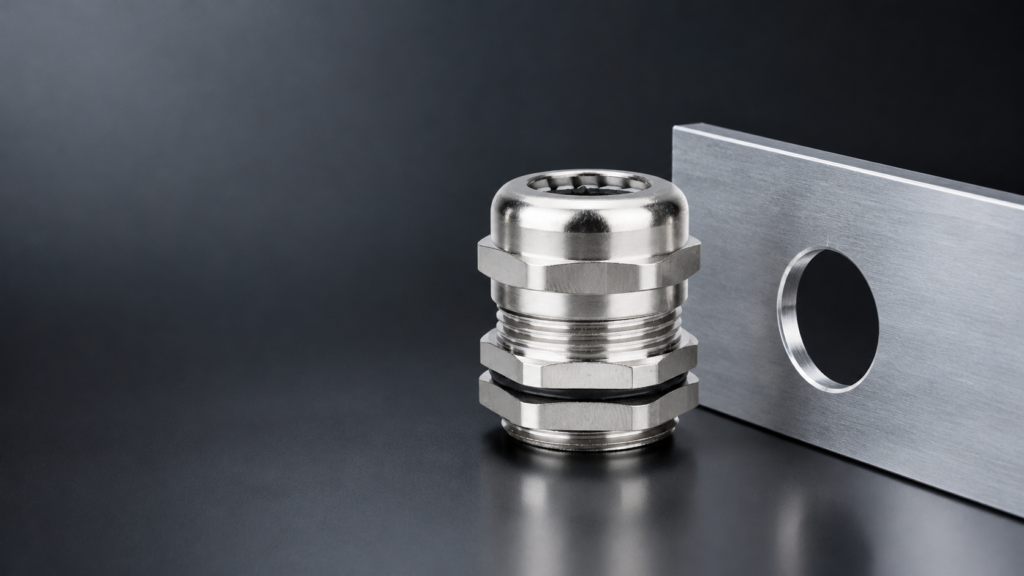
A cable gland hole is the thread outside diameter plus a small clearance — 20 mm thread, 20 to 20.2 mm hole, and the same margin holds across the range. That single rule covers metric and PG glands, because both are parallel threads that seal on the panel face rather than in the thread.
What the rule does not cover is everything that decides whether the gland actually seals after the hole is cut: how the hole was made, how thick the panel is, whether there is a flat face for the gasket, and how close the next hole is. This page gives the hole table first, then the four things that make a nominally correct hole fail.
Fil
Hole (mm)
Fil
Hole (mm)
Fil
Hole (mm)
M14×1.5
14–14.2
M28×1.5
28–28.2
PG11
18.6–18.8
M16×1.5
16–16.2
M30×1.5
30–30.2
PG13.5
20.4–20.6
M18×1.5
18–18.2
M32×1.5
32–32.2
PG16
22.5–22.7
M20×1.5
20–20.2
M33×1.5
33–33.2
PG19
25–25.2
M22×1.5
22–22.2
M36×1.5
36–36.2
PG21
28.3–28.5
M24×1.5
24–24.2
M40×1.5
40–40.2
PG25
32–32.2
M25×1.5
25–25.2
M42×1.5
42–42.2
PG29
37–37.2
—
—
M50×1.5
50–50.2
PG36
47–47.2
—
—
M63×1.5
63–63.2
PG48
59.3–59.5
Hole dimensions are from our standard brass and stainless steel series, where the hole is specified as thread O.D. to O.D. + 0.2 mm. Small threads behave identically: PG7 is 12.5–12.7 mm and PG9 is 15.2–15.4 mm.
Why the Hole Is Always Slightly Larger Than the Thread
Three reasons, and none of them are cosmetic. The thread has a manufacturing tolerance and cannot be assumed to be exactly nominal. The gasket needs somewhere to sit without being squeezed out of position. And the gland has to go in without being driven in — a thread that is forced through a tight hole loses its coating on the way and starts life as a corrosion site.
The 0.2 mm band is deliberately narrow. Wider and the gasket has nothing to bear on at its outer edge; narrower and assembly becomes a press fit. When a supplier quotes a hole range without saying which thread it belongs to, the number is useless — 20.2 mm is a metric number, and the nearest PG thread to it is 20.4 mm, which will not go in. The thread size chart has the diameter for every size in both families if you need to cross-check.
Hole Size Table: Metric Series
Metric threads are the ones most likely to be cut into new panels, so they are also the ones most likely to be damaged by a rushed hole. Note that the hole grows in 1.5 mm steps with the thread pitch, which means a 20 mm hole saw cannot be used for anything other than M20 — there is no metric gland that shares that hole.
Fil
Hole (mm)
Nominal step from previous
Common installation
M14×1.5
14–14.2
Smallest standard body
Sensor and signal entries
M16×1.5
16–16.2
2 mm
Small control cable
M18×1.5
18–18.2
2 mm
Instrument cable
M20×1.5
20–20.2
2 mm
The default entry on most equipment
M22×1.5
22–22.2
2 mm
Power cable, smaller sizes
M24×1.5
24–24.2
2 mm
Where M25 will not fit
M25×1.5
25–25.2
1 mm
Power and motor cable
M28 / M30
28–28.2 / 30–30.2
2 mm
Larger power entries
M32×1.5
32–32.2
2 mm
Main feed on medium panels
M40 / M50 / M63
40–40.2 / 50–50.2 / 63–63.2
Steps of 10 and 13 mm
Incoming supply, large cable
Hole Size Table: PG Series
PG holes are the ones that cannot be fixed later. They are sized in a sequence that has no relationship to whole millimetres — 18.6, 20.4, 22.5, 28.3, 59.3 — so the hole has to be made from the thread designation, never from “about 20 mm”. A PG11 needs 18.6 mm; drilling 18 mm and expecting it to take a PG11 produces a hole that is 0.6 mm tight on the thread and 0.2 mm under the top of the tolerance band.
Fil
Hole (mm)
Nearest metric thread
Why the substitution fails
PG7
12.5–12.7
None at this size
No metric equivalent in the series
PG9
15.2–15.4
M16 (16–16.2)
PG9 hole is 0.8 mm smaller than the metric one
PG11
18.6–18.8
M18 (18–18.2)
Metric hole is undersize for the PG thread
PG13.5
20.4–20.6
M20 (20–20.2)
Metric hole is 0.4 mm undersize
PG16
22.5–22.7
M22 (22–22.2)
Metric hole is undersize
PG19
25–25.2
M25 (25–25.2)
Identical hole, different pitch in the thread
PG21
28.3–28.5
M28 (28–28.2)
Metric hole is undersize
PG25
32–32.2
M32 (32–32.2)
Identical hole, different pitch
PG29
37–37.2
M37 (37–37.2)
Identical hole, different pitch
PG36 / PG42 / PG48 / PG63
47 / 54 / 59.3 / 72
None close
No metric thread lands on these diameters
PG19 and PG25 are the awkward pair. Their holes are identical to M25 and M32 respectively, so a metric gland will physically enter a PG hole and vice versa. It will start, bind within a turn or two, and the fitter will assume the thread is damaged. The hole is not wrong; the thread is. That distinction is worth teaching to whoever runs the punch.
Wall Thickness Changes Which Hole You Need
The same thread needs two different holes depending on what it is going into, and confusing them is the most common drawing error on an enclosure.
Panel arrangement
Hole to cut
What secures the gland
Failure if done wrong
Clearance hole through sheet or cast box
Thread O.D. + 0.2 mm
Locknut on the far side, or a threaded boss
Hole too large: gasket has no bearing face
Threaded (tapped) hole in a thick boss
Tapping drill for the thread
The thread itself
Clearance hole in thick metal: nothing to clamp against
Hole through a thin wall with no locknut
Thread O.D. + 0.2 mm
Nothing — the gland cannot clamp
Gland pulls through or cannot be tightened
Hole through a wall thicker than the thread length
Thread O.D. + 0.2 mm
Nothing — thread does not emerge
No locknut possible, gasket never compressed
That last row is the one that ends in a rework. If the thread does not come out the far side, there is no way to put a locknut on it, and no way to pull the gland down onto the gasket. The gland will sit in the hole and look installed. It will not seal. Check the thread length against the wall before the hole is cut, not after.
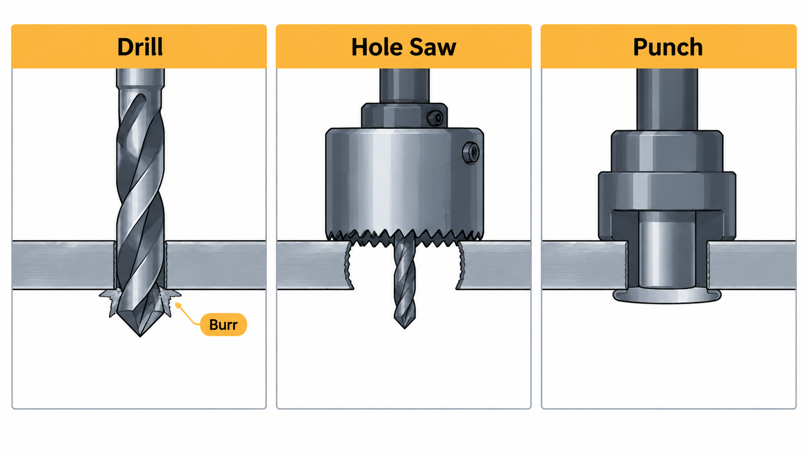
Three ways to make the same hole. The punch gives a clean round edge; the others leave a burr that has to be removed before the gasket will sit flat.
How the Hole Is Made Matters More Than Its Diameter
Two holes measured at 20.1 mm can behave completely differently. A punched hole is round and has a slight roll on one side. A hole saw cuts a hole that is typically a little oversize and can wander if the pilot is not rigid. A hand drill with a step bit leaves a chamfer and, often, a burr on the inside face.
Burr on the sealing face is the single most common cause of a leak on a correctly sized hole. The gasket bridges the burr instead of the panel, so it is compressed everywhere except the point that matters.
Ovality from a worn hole saw removes the clearance on the narrow axis while leaving it on the wide one. The gland goes in tight at two points and loose at the others.
Wandering moves the hole off position. A hole that is 1 mm off is still 20.1 mm in diameter; it is also now too close to the next entry.
Heat from a dull bit or a laser-cut edge can discolour a coated panel and, on galvanised sheet, remove the zinc at exactly the edge that will see water first.
Deburr both faces, then check with a finger rather than an eye. If a fingernail catches, the gasket will too.
The Sealing Face Around the Hole
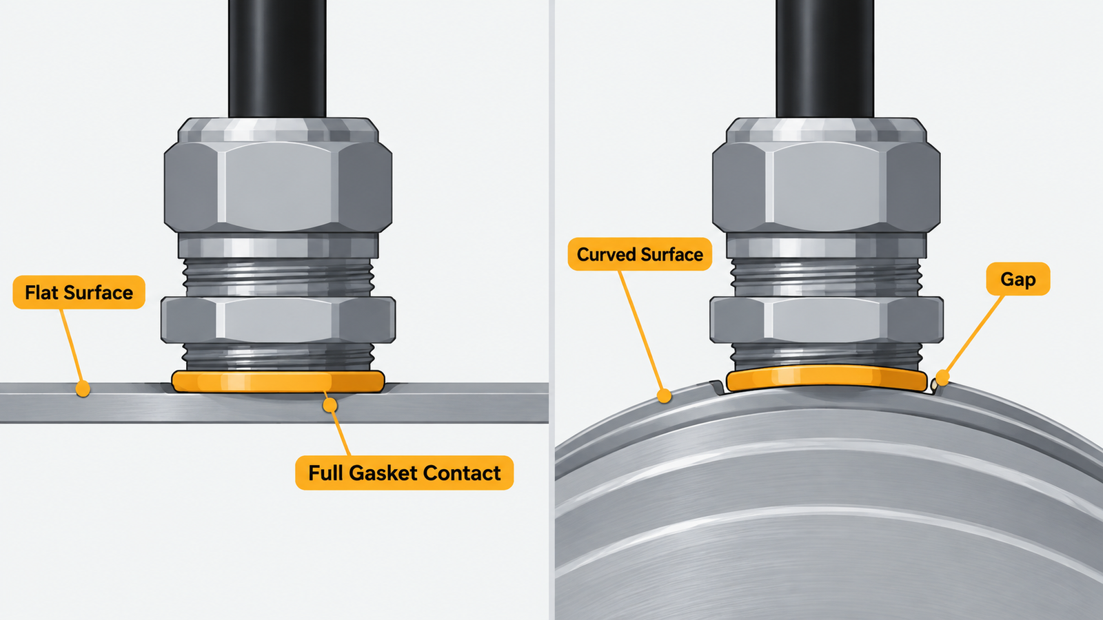
A gland gasket seals against a flat annulus around the hole. The hole can be perfect and the seal still fail because the surface it bears on is not flat, not wide enough, or not continuous.
A gasket needs a continuous flat annulus. On a curved or ribbed surface, only part of the ring makes contact and the rest is a path for water.
On a flat sheet enclosure this is automatic. On a folded profile, a corrugated roof panel or a cast housing with a draft angle, it is not. The standard answers are a flat pad welded or bonded around the entry, a sealing washer with a larger outside diameter than the gasket, or moving the entry to a machined face.
Edge distance belongs here too. A hole placed close to a fold has a gasket that overhangs the bend, and a locknut that cannot get a full grip on one side. As a working rule, keep the hole centre far enough from any edge that the whole gasket ring and the full locknut sit on flat material, and check that rule on the drawing rather than at the drill.
Hole Layout: Spacing and Access
Spacing is decided by the spanner, not by the thread. Two M20 glands on a 25 mm pitch have holes that are correctly sized and glands that cannot both be tightened, because the wrench that fits one cannot reach the other. The across-flats dimension on the datasheet is the number to lay out against — for M20 it is 22 mm, and the hexagon needs clearance on both sides before a second entry is placed next to it.
Two more layout rules that survive contact with a workshop. Leave enough room under the panel for the locknut to be turned, not just to exist; a locknut with no swing space gets tightened with a screwdriver and a hammer. And keep the entry away from the door hinge line and the cable duct, because the cable has to leave the gland without a bend radius tighter than the conductor allows.
When the Hole Is Already Wrong
Existing holes are a constraint, not a reason to accept a bad gland fit. There are four practical recoveries, and only one of them is invisible.
Problème
Recovery
Trade-off
Hole too large
Reducing washer plus a larger gland body, or a stepped adapter
Adds a joint and axial length; must keep the gasket bearing face
Hole too small
Ream or step-drill to size
Only works if the position and edge distance allow it
Hole off position
Weld or plug and re-cut; or fit a larger gland that covers the old hole
Welding disturbs coating; a larger gland changes the cable range
Wrong thread in an existing tapped boss
Adapter to the required thread
Adds a component that has to be recorded in the maintenance file
Whichever route is taken, the entry still has to end up with a flat annulus, a full gasket ring and a thread that the gland can be tightened onto. A recovery that produces a watertight-looking assembly with no compression on the gasket has not recovered anything.
FAQ
What size hole does an M20 cable gland need?
20 to 20.2 mm. Use a 20 mm punch or hole saw and check the result: a hole saw that cuts 20.4 mm leaves the gasket bearing on the very edge of its ring.
Can I drill the hole at exactly the thread diameter?
You can, but you will have to force the gland in and the coating will be scraped off in the process. The 0.2 mm clearance exists so the thread enters without damage.
Do nylon and brass glands use the same hole?
Yes, for the same thread. The thread is cut to the same standard, so an M20 nylon gland and an M20 brass gland both need 20 to 20.2 mm. Cable ranges differ between the two, which is a selection issue rather than a hole issue.
How much clearance do I need between two glands?
Enough for the spanner to turn on both. Lay out from the across-flats dimension plus tool clearance, not from the hole diameter plus a few millimetres.
Does a locknut change the hole size?
No, but it changes the wall thickness the gland can work with. A locknut consumes thread length on the far side, so a thick wall plus a locknut can leave no engagement at all.
If you send us the panel drawing with the cable list, we will mark the hole diameter, thread and clearance for each entry before anything is cut. The brass series and the stainless steel series share this hole table, and the installation guide covers what to do once the holes are in.
PG and metric cable glands are separate thread systems, not two names for one fitting. Flank angles, the nearest-size table, why PG13.5 will not enter an M20 hole, and when an adapter is the right answer.
Apprenez à installer des presse-étoupes étanches avec des guides pas à pas pour une étanchéité IP68 en utilisant des presse-étoupes en nylon, en laiton ou en acier inoxydable de GHX.
How to size an SWA cable gland from the cable itself: the three dimensions that set the inner seal, armour clamp and outer seal, why the same thread has two variants, and how to avoid the wrong-part order.
Nous répondrons à votre demande dans les 24 heures
Nous accordons de l'importance à votre vie privée
Nous utilisons des cookies pour améliorer votre expérience de navigation, vous proposer des publicités ou des contenus personnalisés et analyser notre trafic. En cliquant sur "Tout accepter", vous consentez à notre utilisation des cookies.