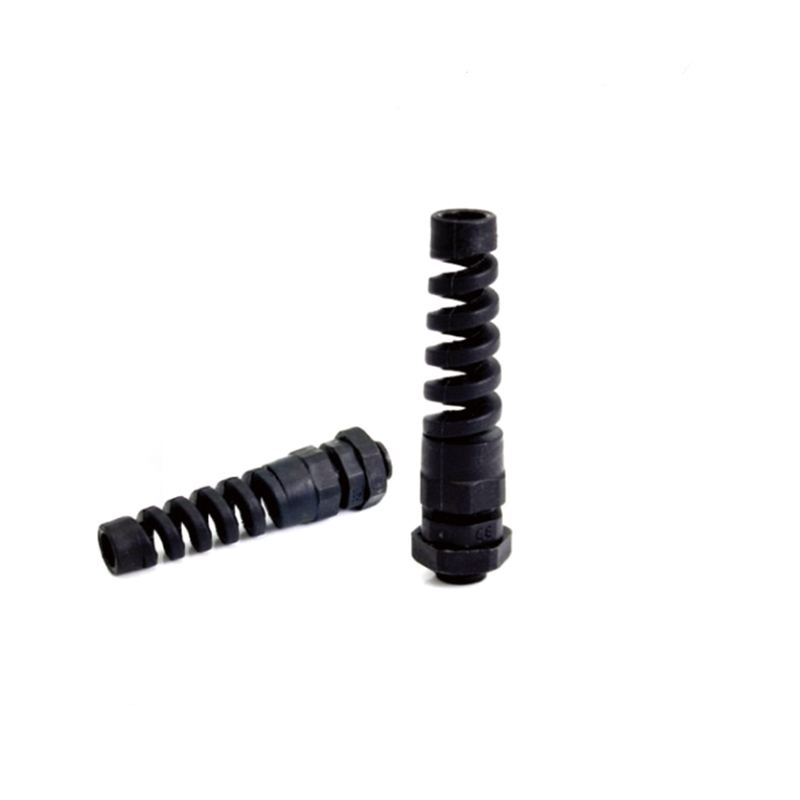
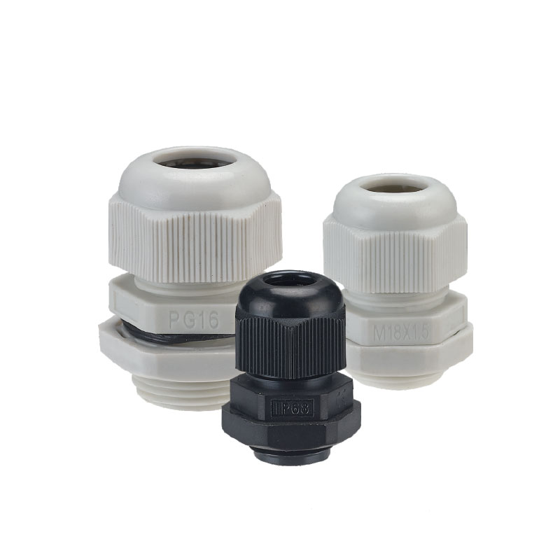
An غدة كابل EMC is a metal cable entry fitting that seals, grips and strain-relieves a cable exactly like a standard gland — and then bonds the cable’s braided or foil screen to the enclosure around a full 360° circumference. That continuous, low-impedance bond is the only thing standing between a screened cable and an antenna: once noise current reaches the enclosure wall, the gland decides whether it drains to earth or radiates across the panel.
It matters most in cabinets built around switching electronics — drives, servos, inverters, switching supplies — and the signal cables that share the same enclosure. Here is how an EMC cable gland works, why the termination method matters more than the material, and how to size, install and verify one.
What Is an EMC Cable Gland?
An EMC cable gland is a screened-cable entry device whose body is part of the grounding path. In addition to the mechanical and sealing functions of a standard gland, it contains a conductive contact element that clamps the cable screen against a metal body bonded to the enclosure, so screen, gland and enclosure become one conductive surface.
A typical assembly contains four functional parts:
Body and cap nut — nickel-plated brass or stainless steel; the conductive path and the mechanical anchor.
Contact element — a spring-finger (crown) ring, a machined contact cone, or a shield clamp that presses the screen around its full circumference.
Sealing insert — EPDM, NBR or silicone, sized to the cable outer diameter (OD).
Clamping insert and locknut — strain relief, pull-out resistance, and enclosure bonding where the panel face has to be bridged.
The screen path must run through metal end to end. A nylon or plastic body offers no conductive path at all, which is why “EMC” and “plastic” cannot appear on the same specification line. If you are still mapping the wider family, the cable gland main types explained guide compares EMC, standard, heavy-duty, armoured and explosion-proof construction.
Why the Screen Has to Be Terminated at the Enclosure Entry
A cable screen works as a Faraday cage only while it is continuous. The moment it stops — at the entry hole, before the conductors reach the terminals — the noise current travelling along the braid has nowhere to go. It couples onto the conductors inside, radiates out of the panel, or returns through anything conductive nearby, motor shafts and bearings included.
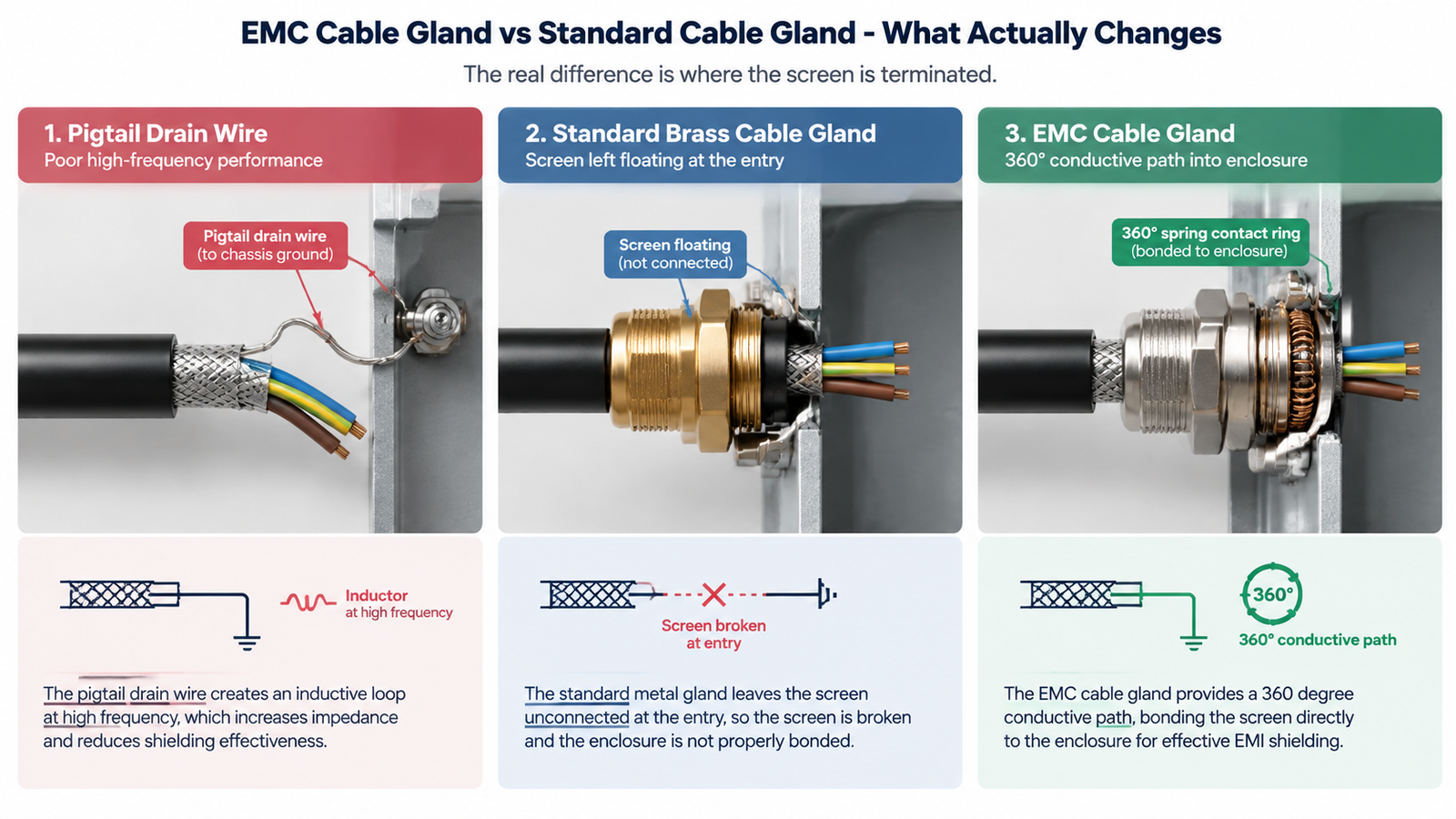
The physics is the part most specifications skip. At the kilohertz-to-megahertz range a drive produces, a short pigtail drain wire is not a ground connection — it is an inductor. Its reactance rises with frequency, so it blocks precisely the noise it was installed to remove. Only a circumferential bond keeps transfer impedance low enough across the band to be useful. In practice, a broken screen bond shows up as encoder and communication faults that appear only when a drive ramps, drifting instrument readings, bearing pitting from shaft currents, and nuisance RCD trips from unintended ground loops.
Termination method
360° contact
High-frequency performance
Stability
Pigtail drain wire
لا يوجد
Poor — inductive above a few MHz
Loosens under vibration
Standard metal gland, screen left floating
لا يوجد
None at the entry — screen broken
Not applicable
Shield clamp or EMC gland plate inside the panel
نعم
جيد
Fixed hardware, needs panel space
EMC cable gland with contact ring
نعم
Good — low transfer impedance
Spring pressure holds under heat cycling
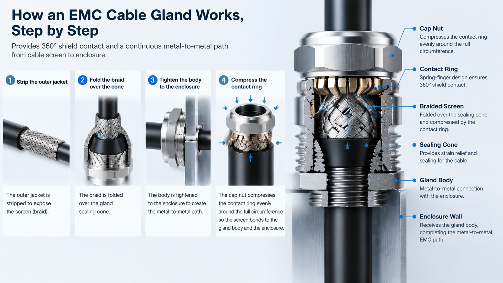
How an EMC Cable Gland Works, Step by Step
The mechanism is simple, and almost every field failure comes from one of the steps below being done carelessly.
Expose the screen. Strip the jacket back to the gland’s stated screen exposure dimension — enough screen to reach the contact element, and no more. Do not nick the braid or score the foil.
Fold the braid over the sealing cone (or seat the foil against the contact insert) so the screen encircles the fitting evenly. A braid bunched on one side gives a partial contact, not a 360° one.
Seat the gland and bond the enclosure. Tighten the body to the enclosure wall so the metal-to-metal path to the panel is established, using a locknut or earth tag where the panel face is painted.
Compress the contact ring to the specified torque. Under-tightening leaves a high-resistance contact; over-tightening crushes the screen and cuts the contact surface into it.
Verify with an instrument, not by eye. Measure continuity and resistance between the cable screen and the enclosure earth. A bonding tester or milliohm meter gives you evidence for the handover file; a visual check does not.
One rule applies to the system rather than the gland: on a drive-fed circuit, terminate the screen at both the drive end and the motor end. A screen bonded at one end only still radiates — the Faraday cage is open. For the full field procedure, including strip and torque checks and the continuity test that proves the bond, see how to install an EMC cable gland.
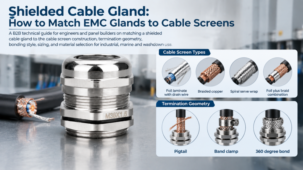
Choosing the gland and terminating the screen are separate decisions, though. If you are still working out which gland suits the cable you actually have — foil with a drain wire, braided copper, spiral wrap or a foil-and-braid combination — the construction-by-construction breakdown is in matching a shielded cable gland to the screen construction, together with the bonding rules and sizing checks that go with it.
EMC Cable Gland vs Standard Cable Gland: What Actually Changes
The difference is not the material and not the IP rating. It is where the screen is terminated.
العامل
Standard cable gland
غدة كابل EMC
Primary function
Sealing, retention, strain relief
Sealing, retention, strain relief plus screen termination
Screen continuity
None by design
360° conductive path to the enclosure
Cable type
Unshielded cable
Shielded, screened or braided cable
Body material
Nylon PA66, brass, stainless steel
Conductive metal only — nickel-plated brass or stainless steel
Installation sensitivity
Mechanical and sealing quality
Screen contact quality and enclosure bonding
Typical applications
Power distribution, lighting, junction boxes
VFD and servo feeders, instrumentation, panel communications
A standard gland is still the right answer for unshielded power cable, lighting circuits, utility wiring, and enclosures where the screen is properly terminated on a dedicated clamp or bonding bar just inside the panel. Paying for EMC hardware does nothing for a cable that is not part of an EMC strategy in the first place. For the specification-level breakdown and the indicative FOB price gap, see EMC cable gland vs standard cable gland.
Materials, Threads and Contact Designs to Specify
Nickel-plated brass is the default: the brass body carries the current, and the plating keeps the contact surface from oxidising so contact resistance stays stable over years of washdown chemicals and saline air. Stainless steel 316 is for environments — chloride, acid, continuous washdown, marine or offshore duty — that would attack brass no matter how well it is plated.
“EMC cable gland” describes a function rather than a single product, so check which contact design the datasheet actually specifies — they do not perform identically.
Contact design
How it contacts the screen
Where it fits best
Contact spring / spring-finger (crown) ring
Compressed fingers grip the folded braid around the full circumference
Industrial VFD and panel work — fast to install, tolerant of assembly variation
360° contact cone or contact area
Screen clamped against a machined cone with a large contact surface
Demanding high-frequency work where the lowest, most uniform contact resistance matters
Shield clamp
A clamp bar presses the screen against a saddle
Retrofit work and larger cable diameters
Conductive insert in a plastic shell
A metal insert carries the screen through a non-metallic body
Light-duty, cost-driven enclosures only
Option
Ingress protection
نطاق درجة الحرارة
Threads and cable range
الملاحظات
Nickel-plated brass EMC gland with 360° contact spring
Indicative FOB Ningbo / Shanghai: US$0.90–6.50 per pc for nickel-plated brass EMC glands, 1,000 pcs per size, standard export packing. Stainless steel and custom-thread versions are quoted separately.
Thread standard decides whether the gland seals at all. Metric (M20×1.5) dominates new equipment, PG survives on older European machinery and retrofit panels, and NPT is standard on North American equipment and instrument ports. They are not interchangeable — PG13.5 is not an M20 substitute, because the outside diameters differ and the sealing face sits in a different position. Dimensions are in the cable gland thread types guide.
For the sealing side of the specification, work from real exposure rather than habit: IP66 for weather, IP68 where immersion or washdown is possible. The guide to choosing the right IP rating sets out how the two are tested.
How to Choose the Right EMC Cable Gland
Confirm the cable is screened — and where the screen should terminate. If the screen is already clamped to an EMC plate or grounding bar inside the cabinet, a standard metal gland may be sufficient. If the entry point is the termination point, specify EMC construction.
Measure the actual cable OD, not the nominal size. Sit the cable in the middle third of the clamping range; at the extreme of the range you get either weak contact pressure or a compressed, damaged screen.
Match the thread to the enclosure or to the gland you are replacing. This is the most common cause of a rejected order and cannot be corrected on site.
Choose the material from the environment, and the IP rating from the exposure. Nickel-plated brass covers most industrial and outdoor work; 316 stainless steel covers chloride, acid and washdown duty.
Check the enclosure bonding path. A painted or insulated panel face isolates a perfect gland. Use a locknut, earth tag or masked bonding surface, and confirm the panel itself is earthed.
Confirm the paperwork before you order on hazardous-area or export projects: ATEX / IECEx for Ex zones, and CE, RoHS or REACH declarations for European markets.
Common mistake
What it costs you
Pigtail drain wire instead of a 360° contact
The screen becomes an antenna above a few MHz; encoder and comm faults appear under load
Nylon gland on a screened cable
No conductive path at all — the screen is open at the entry
Cable at the edge of the clamping range
High contact resistance and degraded sealing, even on an IP68-rated gland
Over-tightening the cap nut
Crushed braid or foil, broken contact, damaged screen
Gland fitted through a painted panel face
Shield electrically isolated; the installation looks correct and measures badly
Where EMC Cable Glands Pay for Themselves
The strong cases are all one case: a shielded cable entering an enclosure that also contains high-frequency switching, or carrying a low-level signal that noise would corrupt — VFD motor cables, servo and encoder feedback lines, instrumentation and weighing circuits, panel communications, solar inverters, and data centre or telecom cabinets with dense cable entries.
When a machine starts eating encoder faults, drifting readings or motor bearings, the drive usually gets the blame and the cable entry gets ignored. The cheapest diagnostic is also the fastest: measure the resistance between the screen and the enclosure earth at the entry point.
Sourcing Notes: MOQ, OEM Marking and Documentation
Standard nickel-plated brass EMC glands ship from 1,000 pcs per size with no tooling charge, and trial orders of 100–500 pcs are available on stock sizes so you can validate the fit before committing to volume. Stainless steel and Ex-certified glands carry a 300 pcs per size MOQ because they are machined to order, and mixed containers are built across sizes and types so one 20 ft load ships at a single freight cost. For private-label orders, four inputs are needed before quoting: gland type and thread standard, cable OD range, the body marking you want laser-etched, and the packing format. Documents ship with the first order — IP68 immersion test report to IEC 60529, CE declaration, RoHS and REACH statements, brass and stainless steel material certificates. If your market requires EN 50262, IEC 62444 or UL 514B, raise it at the inquiry stage, because it can change the body design rather than just the paperwork.
Conclusion
An EMC cable gland earns its place through one property: it keeps the cable screen continuous all the way to the enclosure wall, around the full circumference, with a bond that survives vibration and heat cycling. Plating, IP rating and thread standard support that function — none of them replace it.
Four decisions decide whether the shielding works: specify metal, size the cable to the middle of the clamping range, match the thread, and confirm the enclosure bonding path. Then tighten to the specified torque and measure the screen-to-earth resistance instead of trusting a visual inspection.
Send us the gland type, the thread standard and your annual volume, and our engineering team will return a specification drawing, a certificate pack and an FOB quotation within one working day — contact us here.
الأسئلة الشائعة
What is an EMC cable gland used for?
It is used on shielded, screened or braided cable wherever the screen has to be bonded to the enclosure at the cable entry point — most often VFD and servo drive feeders, instrumentation and weighing circuits, panel communications, solar inverters, and data centre or telecom cabinets.
How does an EMC cable gland work?
The installer exposes the screen, folds the braid over the gland’s sealing cone (or seats a foil screen against the contact insert), and the cap nut compresses a spring-finger ring or contact cone around the full circumference. That creates a metal-to-metal bond from screen to gland body to enclosure, so interference current drains to earth instead of coupling onto the conductors.
Can a standard metal cable gland replace an EMC gland?
Only if the screen is terminated somewhere else, such as on an EMC gland plate or grounding bar inside the cabinet. A standard metal gland seals and anchors the cable, but it does not provide a designed 360° screen contact at the entry, so on VFD, servo and instrumentation circuits it leaves the shielding strategy unfinished.
Does the screen need to be grounded at both ends?
On drive-fed circuits, yes — at the drive end and the motor end, so the Faraday cage is closed. Grounding only one end leaves the noise with nowhere to return, which is why single-ended screen termination so often fails to fix the interference.
Are EMC cable glands waterproof, and what do they cost?
Nickel-plated brass EMC glands are typically rated IP68 as standard to IEC 60529; sealing depends on the cable OD matching the clamping range and on correct tightening torque. Indicative FOB Ningbo / Shanghai pricing is US$0.90–6.50 per pc at 1,000 pcs per size, with trial orders of 100–500 pcs available on stock sizes; stainless steel and Ex-certified models carry a 300 pcs per size MOQ.
Match an EMC cable gland to the cable screen: foil, braid, spiral and combination constructions, termination geometry, bonding rules and sizing on jacket OD.
غُدَّة الكابلات المصنوعة من الفولاذ المقاوم للصدأ هي مكونات أساسية تُستخدم لتوصيل الكابلات بالمعدات الكهربائية وإحكام غلقها. فهي تحمي الكابلات من الإجهاد الميكانيكي والمخاطر البيئية مثل الرطوبة والغبار والتعرض للمواد الكيميائية. على عكس الغدد المصنوعة من البلاستيك أو النحاس الأصفر، توفر غدد الكابلات المصنوعة من الفولاذ المقاوم للصدأ متانة فائقة ومقاومة للتآكل والقوة، مما يجعلها مثالية ل [...].
كملحق أساسي لتوصيل الكابلات والمعدات، تلعب غدة الكابلات دورًا حيويًا في حماية الكابلات ومنع دخول الماء والغبار وتوفير التأريض. سواءً في الأتمتة الصناعية أو التحكم الكهربائي أو البحرية أو التعدين أو غيرها من البيئات الصعبة، فإن اختيار غدة الكابلات المناسبة أمر ضروري. اليوم، دعونا نلقي نظرة فاحصة على الأنواع الرئيسية [...].
نحن نستخدم ملفات تعريف الارتباط لتحسين تجربة التصفح الخاصة بك، وعرض إعلانات أو محتوى مخصص، وتحليل حركة المرور لدينا. بالنقر على "قبول الكل"، فإنك توافق على استخدامنا لملفات تعريف الارتباط.