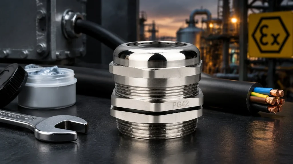
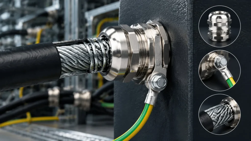
An explosion proof cable gland arrives certified and leaves the store as a compliant component. What happens on site is a different question. The certificate covers the gland, not the assembly you build around it. Installation is where a certified part either becomes a certified termination or becomes an uncertified one that looks identical from outside.
This guide covers installation and acceptance only: preparation, assembly order, the barrier compound step, thread engagement, tightening, and the inspection evidence.
An Ex gland installation is a compliance record, not a fitting job
IEC 60079-14 governs the design, selection, erection and initial inspection of installations in explosive atmospheres. The word that matters for installers is erection. The standard does not say “fit the gland properly”; it says the installation must be inspected before commissioning, and the inspection has to be recorded.
Ten glands fitted perfectly but undocumented is a weaker position than ten glands fitted well with photographs, measurements and a signed inspection sheet. “The fitter is experienced” does not survive the meeting when an engineer asks why a Zone 1 entry should be accepted. Treat the job as two outputs: a mechanical assembly and a record.
The three interfaces nobody can inspect afterwards
Most of an Ex gland assembly stays verifiable: the shroud, the body, the earth tag. Three interfaces cannot be verified once the gland is closed, and those are where failures originate.
Interface
What it decides
How to verify before closure
Evidence to keep
Entry thread engagement
Whether the flame path or the IP seal at the enclosure wall is complete
Compare gland GL against wall thickness plus locknut and washer; confirm the enclosure’s certified entry depth
Measured GL, wall thickness, photo of the thread before assembly
Inner seal on the bedding
Whether water and gas can travel under the armour along the bedding
Seal must sit on clean bedding, not on armour wires; bedding undamaged
Photo of the stripped cable with seal positioned
Compound fill (barrier glands)
Whether gas can pass through the cable interstices into the enclosure
Fill from the crutch outward until the compound seats against the armour cone; no voids between cores
Compound batch, mix time, ambient, cure start and finish
Every field failure that ends in a shutdown traces back to one of these three. Everything else on the gland is visible or replaceable.
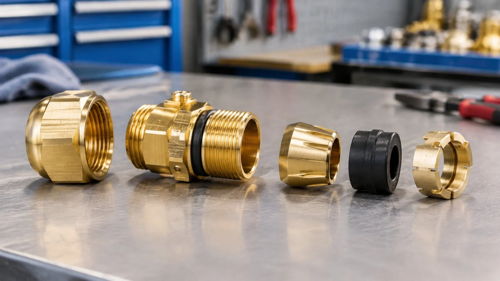
A flameproof gland partly assembled on the bench, with the armour cone, clamping ring and inner seal laid out in fitting order. Once the body is closed, the seal position and the cone seating can no longer be checked.
Pre-installation checks that decide the rest of the job
Five minutes at the bench prevents most of the rework described later.
Certificate against the entry point. Confirm the marking matches the enclosure: protection concept, group, EPL, temperature range and entry thread. A gland certified for another protection concept is not interchangeable, as explained in Ex d vs Ex e cable glands.
Cable against the gland range. Measure the actual sheath and bedding diameters. Reel labels drift; a gland selected on nominal size is a common first error.
Components against the drawing. Lay out the full stack and count against the exploded view. Missing parts are usually discovered after the cable is cut.
Thread condition. Inspect the gland thread and the enclosure entry for paint, burrs, swarf and damage. A painted entry thread on an Ex d enclosure is a flame-path defect, not a cosmetic one.
Tools. Two spanners that fit the hex flats, a calibrated torque tool if required, and the compound kit if applicable.
Assembly sequence by gland type
The order is not stylistic. Getting it wrong means stripping the cable twice, or finding a component that should have been threaded on first.
Strip sheath and armour, seat cone, then strip bedding to reach cores
Strip sheath only; no armour
3
Fit earth tag and locknut at the entry
Fit earth tag and locknut; entry component can be installed before the resin pour
Sealing washer and locknut
4
Tighten body onto entry, then armour clamp
Separate cores, pour compound, cure fully
Tighten body onto entry
5
Tighten dome nut to compress the outer seal
After cure, tighten dome nut over sheath seal
Tighten dome nut over the seal
6
Fit shroud, record continuity
Fit shroud, record continuity and cure record
Fit shroud, check IP face
On a barrier gland, step 4 is where jobs are lost. Everything before it can be undone; the pour cannot.
Barrier glands: where the compound step decides the outcome
A barrier gland exists because a compression seal on the outer bedding cannot stop gas travelling inside the cable. Compound is packed around the individual cores, filling the interstices, so gas has no continuous path from the cable’s far end into the enclosure.
Four rules govern that step, and every one is a documented failure mode:
Cores must be separated before the pour. If they are still taped or bundled, compound sits around the bundle instead of between the cores and the barrier is decorative.
Fill from the crutch outward. Packing from the gland end leaves a void where gas enters the core bundle.
Respect the cure window and ambient minimum. Barrier instructions commonly specify something in the order of 24 hours above roughly 10 °C before energising; the exact figures come from the compound and gland documentation, not from this page.
Do not top up a part-used mix. Pot life shortens sharply as ambient rises, and a fresh mix added to a partly cured tube may not bond.
After cure the assembly is effectively permanent, which is why the rework section below exists.
Thread engagement: measure it, don’t count it by eye
The “five full threads” figure circulates widely and comes from North American conduit-entry practice. It is a reasonable floor, not a specification. What governs is the enclosure’s certified entry and the gland’s thread length.
Do the arithmetic before the gland goes in:
Take GL (thread length) from the datasheet — on our range from 7 mm at M14/PG7 to about 15 mm at the largest sizes.
Add the wall thickness at the entry, the locknut, and any washer the entry allows.
The remainder is the engaged length, which must satisfy the certified minimum and be full thread.
Two brass-specific details matter. A brass external thread engaging a steel female thread deforms before the steel does, so short engagement in brass strips rather than stretches. And on flameproof entries the thread is the flame path: tape, sealant, paint and uncertified adaptors all modify it. If the entry is certified for metal-to-metal contact, a nylon washer at the shoulder changes the assembly. For dimension sources, see the cable gland thread size chart.
Tightening without inventing torque numbers
Published torque tables for Ex glands are often quoted as if universal. They are not: the value depends on thread size, seal hardness, body material, whether there is a metal-to-metal stop, and where the cable sits in its range. The same M25 gland can need materially different values on two different seal compounds.
Use the manufacturer’s figure where one exists, and outcome criteria where it does not:
The seal has stopped moving and shows no extrusion past the nut.
The cable cannot be rotated by hand and does not move axially under a firm pull.
Armour wires do not shift when the body is counter-held and the clamp re-checked.
No thread is deformed and no body flat is marked by the spanner.
Under-tightening lets water travel along the sheath and lets the cable creep; over-tightening extrudes the seal and can crack a brass dome nut. Both are progressive, which is why the torque guide treats tightening as a procedure rather than a number.
Initial inspection and the evidence file
IEC 60079-14 requires initial inspection before commissioning; IEC 60079-17 defines the periodic grades afterwards. For a new installation the useful output is a file per entry point, not a tick on a cable schedule.
Item
What is checked
Evidence that satisfies an auditor
Gland identity
Model, certificate number, batch, marking against the entry point
Photo of the marking plus certificate reference on the schedule
Cable data
Type, construction, measured sheath and bedding diameters within range
Measured values entered, not nominal sizes copied
Entry
Thread form, engaged length, no tape or paint, washer permitted or not
Measured GL and wall thickness; photo before assembly
Internal assembly
Seal on bedding, cone seating, wire distribution, no nicked insulation
Photo taken before the body is closed
Barrier
Compound batch, mix time, ambient, cure start and finish
Signed pour record with times
Electrical
Armour or screen continuity to the enclosure earth bar
Two entries are frequently missing in practice: the pre-closure photograph and the cure record. Both are cheap at the time and impossible to reconstruct later.
Rework after closure, and what it really costs
The reason to slow down before closure is that four common defects cannot be corrected in place.
Wrong gland size found after a cure. The barrier is inside the gland, so removing it means cutting the cable. The cost is a joint or a re-pull, not a gland swap.
Wrong cone profile for the armour. Stepped cones suit round wires; grooved cones suit braid, tape and strip armour. If the wires do not seat the clamp will not grip, and on a cured gland the fix is again the cable.
Damaged flameproof entry thread. A cross-threaded Ex d entry is a damaged flame path. The gland is replaced and the entry assessed; it is not cleaned up with a file.
Entry opened up to a larger size. Enlarging a hole in a certified enclosure changes a certified item and needs the manufacturer’s position in writing, not a step drill.
One defect is cheap to fix but often left: a missing shroud or earth tag. It does not appear in a photograph taken from the wrong angle.
A slow, recorded install is cheaper than a fast one with a cured mistake in it. Where the cable is armoured, the same discipline applies to the clamping sequence in the armoured cable gland guide. If the protection concept is still open, start from what an explosion proof cable gland is and the hazardous area selection process. Our CMP-pattern barrier glands ship with the compound kit and installation drawing; send us your entry schedule and we will confirm which entries need a barrier.
A technician recording an inspection on a hazardous-area cable schedule beside a completed flameproof entry. The written record, not the visual appearance, is what an initial inspection is judged on.
Frequently asked questions
How many threads must be engaged on an explosion proof cable gland?
No single number applies to every gland. The “five full threads” figure is a North American practice floor. The governing requirement is the certified entry plus the gland’s thread length, so calculate engaged length as GL minus wall thickness minus locknut and washer, then confirm the minimum in the gland documentation.
Can I use thread tape on an Ex d cable gland?
No. On flameproof entries the thread forms part of the flame path, and tape or sealant changes the joint. Paint and uncertified adaptors are treated the same way. Where sealing is needed at the shoulder, use only a washer the certificate permits.
How long must barrier compound cure before energising?
Cure time and minimum ambient come from the compound supplier and gland instruction sheet — commonly around 24 hours above roughly 10 °C, but confirm the figure for the specific kit. Energising early is a non-conformance even if the resin looks set.
Does an Ex e gland need sealing compound?
No. Increased safety glands seal by compression and rely on maintaining the enclosure’s IP rating; the entry thread is a mechanical connection, not a flame path. Barrier compound is a flameproof measure, not a general upgrade.
What happens if the gland’s certificate covers a different thread?
The installation is not covered. Certification is specific to the gland, thread form and marking on the certificate. A gland of the right size but another thread family or protection concept must be replaced before commissioning.
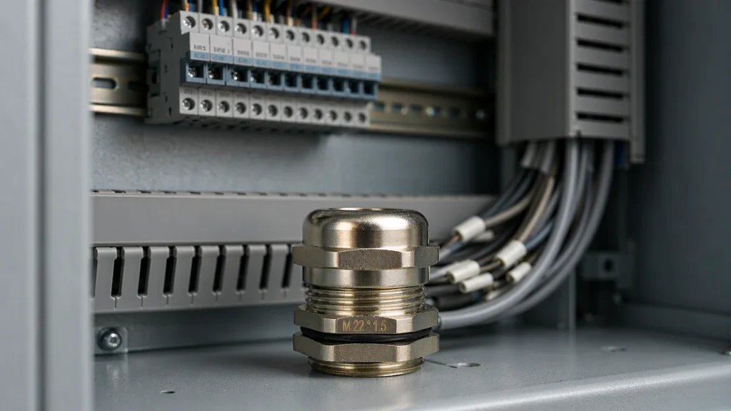
A control panel cable gland is usually chosen by hole size and paid for thirty centimetres later at the terminal block. Entry height, bend radius, door routing, shield bonding and the marking that makes a panel traceable.
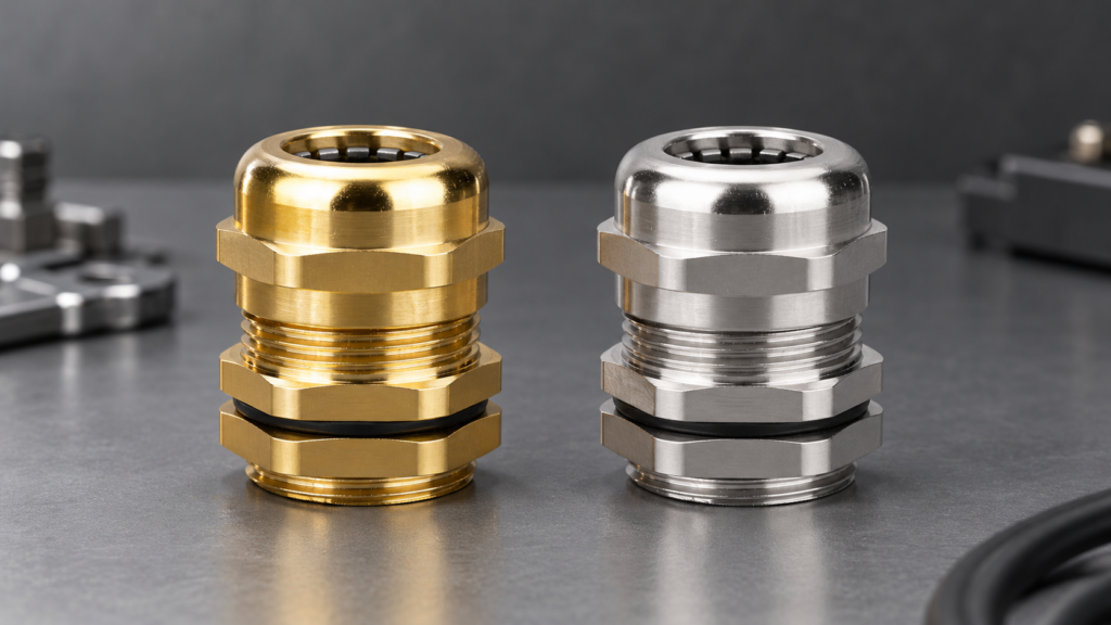
Brass and stainless steel cable glands compared size for size: weight, conductivity, temperature, galling, chloride failure mode, galvanic coupling and what the price gap actually buys.
How to earth an armoured cable gland properly: earth tag options, contact resistance across the stack, whether the armour can be the CPC, and how to interpret the test reading.
Usamos cookies para aprimorar sua experiência de navegação, veicular anúncios ou conteúdos personalizados e analisar nosso tráfego. Ao clicar em "Aceitar tudo", você concorda com o nosso uso de cookies.