Presse-étoupe étanche
How to Choose Split Cable Glands: 8 Selection Steps
Choose split cable glands correctly by matching cable diameter, connector clearance, mounting, IP rating, material, environment, and approvals.
Lire la suite
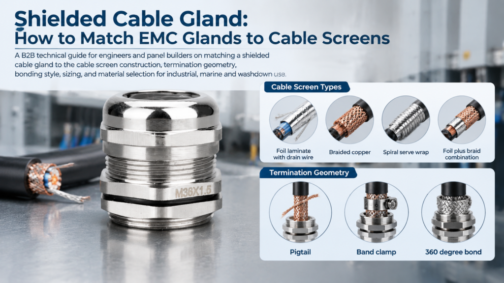
A shielded cable gland is only as good as the bond it makes to the cable screen. You can order the right part number, seal it to IP68, and still lose most of the screening because the braid was twisted into a pigtail or the gland landed on a painted enclosure wall. The gland is not a fitting that happens to be metal — it is the point where the screen stops being a wrap of copper and becomes part of the enclosure potential.
This guide covers the cable side of that decision: how the common screen constructions behave, which termination geometry holds up at radio frequencies, when to bond at one end or both ends, and how to size a gland without trapping yourself. The gland’s own mechanism is covered in our article on what an EMC cable gland is and how it works.
A standard metal gland seals, grips and provides strain relief. What it does not guarantee is a low-impedance circumferential path from the screen to the enclosure — many designs have no component shaped to press against a braid.
Screening works because the screen carries interference current back to its source as a return current flowing over its outside surface, and that only happens while the screen behaves like a continuous conductor. Introduce a break — a length of thin wire, a loose spiral, an unpainted gap — and the bond acquires series inductance that increasingly blocks the interference current as frequency rises. The screen stops behaving like a short circuit and starts behaving like an antenna. Published cable-assembly measurements routinely report a 20–40 dB improvement above 100 MHz when a pigtail bond is replaced by a full circumferential bond on the same cable. Coverage percentage and shield material matter far less than that single decision.
An EMC gland earns its place by providing a clamping surface that touches the screen around its whole circumference, close to the enclosure sheet.
Termination technique has to follow construction. A gland that is perfect for a braid can be useless on a foil.
| Screen Construction | How It Is Built | Typical Coverage | Strongest Frequency Band | How the Gland Should Contact It |
|---|---|---|---|---|
| Foil laminate with drain wire | Aluminium/polyester tape wrapped over the cores, with a bare tinned drain wire in permanent contact with the foil | Complete wrap by construction | High frequency, above roughly 10 MHz | Drain wire landed on an earth terminal; foil folded back too, only if the gland design permits it |
| Braided copper | Copper strands woven into a tube over the cores | Usually quoted as optical coverage, typically 40–95% | Low to mid frequency, plus mechanical durability | Braid dressed back over the gland cone and compressed circumferentially |
| Spiral (serve) wrap | Copper strands wound helically rather than woven | Pitch-dependent, typically 60–80% | Flex life rather than attenuation | Smooth cone or clamp edge that cannot cut individual strands |
| Foil plus braid | Foil over the cores with a woven braid over the foil | Foil wrap inside, braid coverage outside | Broadband — foil handles high frequency, braid handles low | Braid clamped circumferentially; foil bonded either through the same clamp or through its drain wire |
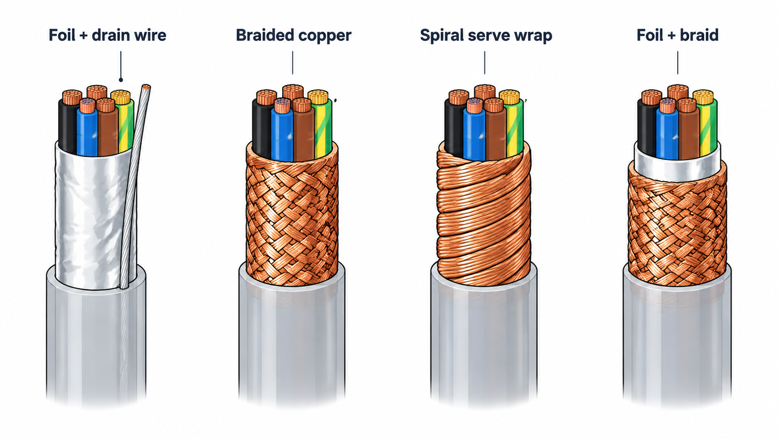
Two of these are frequently confused. Foil is a continuous wrap, so it presents no apertures to high-frequency leakage, but it is fragile and tears if clamped directly. Braid is tough and easy to clamp, but its weave leaves small gaps — which is why combination cable exists. When a datasheet claims 100% coverage, it usually means the foil layer, not the braid.
Every practical termination is a compromise between bond quality and build convenience. Sorted from worst to best in high-frequency terms:
| Termination Method | Contact Geometry | Frequency Range Where It Still Works | What It Suits |
|---|---|---|---|
| Braid twisted into a pigtail, bonded to a stud or shell | A single point, with the whole bond in series | Low frequency only; performance falls away as the exposed length grows | Legacy retrofits and prototypes where no proper hardware exists |
| Drain wire landed on an earth terminal | A single point through a thin conductor | Low and moderate frequency, short runs, modest noise | Foil-shielded control, sensor and instrumentation cable |
| Braid clamped by a band or by the gland cone inside the body | Full circumference at the point of clamping | Wide band; the standard industrial answer | Enclosure entry where a metal gland, gland plate or conductive backshell is available |
| Dedicated conductive contact ring or spring with the screen dressed back over the cone | Full circumference, short path from cable entry to enclosure sheet | Widest band and the lowest bond impedance | VFD and servo cable, industrial Ethernet near drives, EMC-test-critical builds |
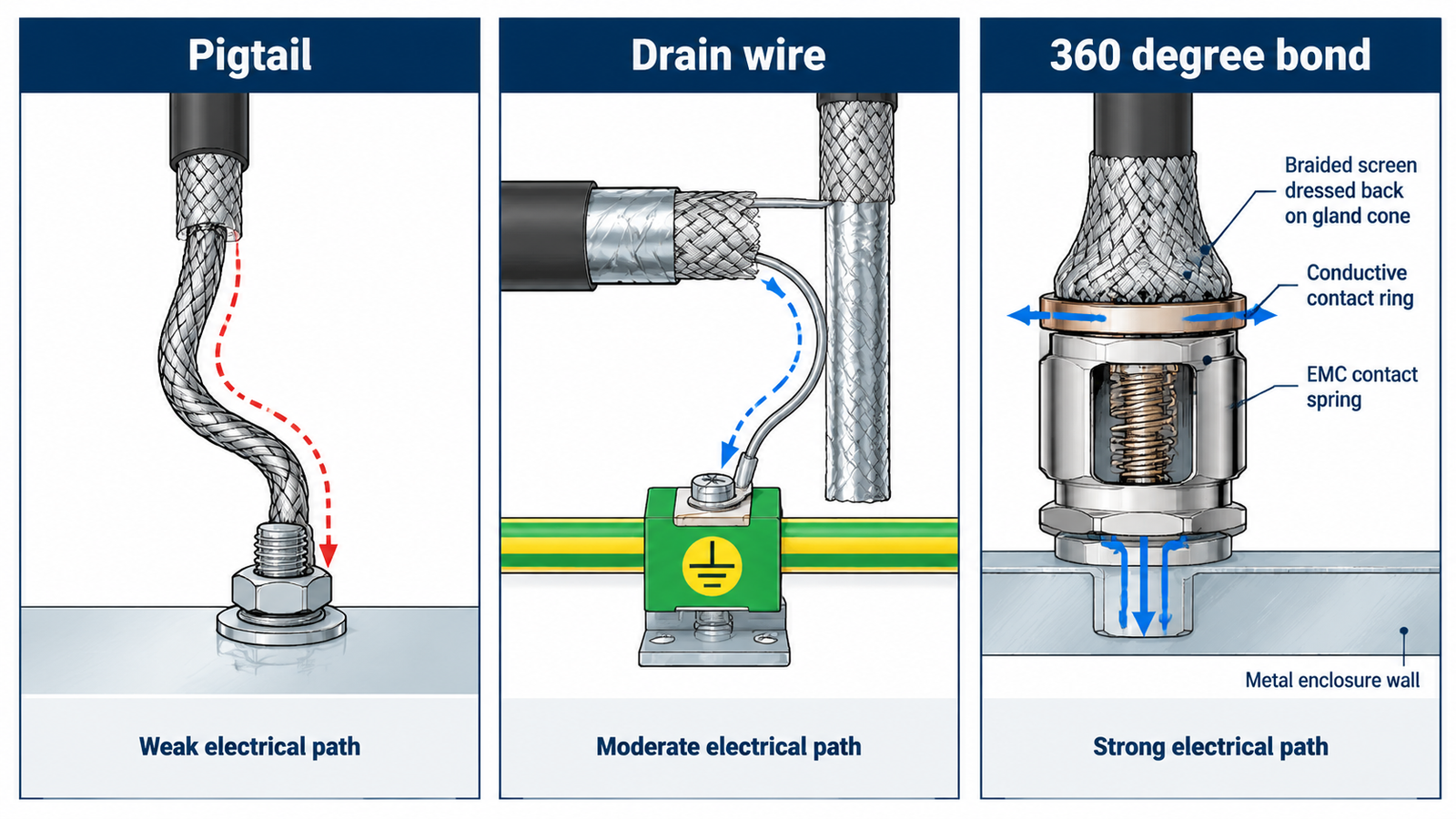
The step from row one to row four is the difference between a cable screened in the catalogue and one screened in the cabinet. Current-carrying capacity, bending radius and gland material all stay the same — only the geometry of the contact changes.
Where a panel is thickness-limited, a nickel-plated brass body with a conductive contact insert, such as the M22 shielded gland, keeps the whole path inside a normal panel thickness.
Foil-shielded cable is the awkward case, and it turns up constantly in control and instrumentation work because it is inexpensive and terminates easily in a terminal block. The foil is only microns thick: it cannot be clamped or crimped directly, and tears if a cone is screwed down onto it. So the manufacturer supplies a drain wire, and that wire becomes the bond.
Recognise what that is: a single-point bond through one thin conductor, electrically much like a short pigtail. Reasonable for sensor loops, thermocouples and low-speed control in moderate noise; the wrong starting point for a drive-fed motor cable.
If you must use foil cable in a noisy area, keep the exposed drain wire as short as the gland allows and avoid loose loops of screen inside the enclosure — a loop both raises impedance and picks up noise.
Bond strategy depends on frequency rather than preference.
Bond at both ends when the cable carries a drive output, a servo signal, industrial Ethernet, or anything operating above roughly 1 MHz. At those frequencies the skin effect keeps interference current on the outside of the screen and the signal return on the inside, so the two do not share a path. A screen bonded at one end only has a floating end, and a floating end radiates.
Bond at one end for low-frequency analogue runs — thermocouples, strain gauges, audio — and for cables linking equipment with different earth potentials, such as two buildings with separate earth systems. Here the dominant risk is a circulating current appearing directly as noise on the signal, and the cable is not screened at radio frequencies in this configuration.
If a project has both problems, do not weaken the bond. Bond at both ends and deal with the loop separately, using a common-mode choke or a differential receiver. Our comparison of EMC and standard cable glands sets out what else changes when you move to a screened build.
| What to Check | Why It Decides the Result | Common Error |
|---|---|---|
| Outside diameter over the jacket | The seal and the clamping insert are sized on the jacket diameter | Ordering against conductor cross-section, such as “2.5 mm²” |
| Added thickness of the dressed-back screen | Folding the braid over the cone adds material at the entry point | Sizing on the bare jacket diameter, then finding the braid will not seat |
| Clamping range of the chosen size | Thread size and clamping range are independent variables | Assuming two glands with the same M20 thread must accept the same cable |
| Entry thread against the panel hole | The gland has to match the enclosure and reach the earth path | Mixing PG and metric entries, or fitting into an oversized hole |
| Earthing provision at the panel | The bond is only as good as the metal it lands on | Relying on a painted or anodised surface to carry the screen current |
For larger motor and feeder cables, a longer body is usually the practical choice because it gives the screen more room. An IP68 nickel-plated brass body in the larger metric sizes, such as the M36 shielded gland, accommodates a dressed-back braid without forcing the fit.
A correct termination into a poor ground path is still a failed screen. Three things decide whether the path holds.
Sealing and screening compete for space: the seal compresses on the jacket while the screen compresses onto metal, and neither should be sacrificed for the other. Check that the ingress protection you need is stated for the exact size and cable range you are ordering, because a rating quoted for one size does not transfer to the series.
| Mismatch | What Happens | Fix |
|---|---|---|
| Braid twisted into a pigtail | Bond impedance rises with exposed length; screening collapses at high frequency | Dress the braid back over the cone and clamp it circumferentially |
| Foil cut back and discarded | No bond to the foil remains; only the drain wire, if it survived | Keep the drain wire and land it, and fold the foil back where the gland allows |
| Gland fitted to a painted or anodised panel | The screen has no conductive route into the enclosure | Cutting earth nut or star washer, or mask the hole to bare metal |
| Single-end bond on a drive cable | The floating end re-radiates the noise you were trying to contain | Bond at both ends and manage the loop separately |
| Sized on conductor cross-section | The seal never compresses correctly and strain relief is lost | Size on jacket outside diameter with the screen dressed back |
| Non-metallic gland on shielded cable | No bond path exists at all, regardless of how well the screen is prepared | Use a nickel-plated brass or stainless steel gland |
Most of these are caught in the first ten minutes of assembly rather than in a test chamber, which is why the checks belong on the drawing. Our step-by-step walkthrough of installing an EMC cable gland covers the sequence itself, including how to confirm the bond is real before the panel closes.
The choice of shielded cable gland matters less than what happens at the moment the screen meets metal. Match the gland’s contact geometry to the screen construction, keep the transition from screen to enclosure as short and as circumferential as the hardware allows, decide the bonding strategy by frequency rather than habit, and size on the jacket diameter with the screen dressed back.
If you are specifying screened cable entry for a panel, machine or marine installation, send us the cable construction, the outside diameter and the entry thread and we will confirm the gland, the contact element and the earthing hardware to match. Talk to our team with your cable datasheet.
A cable entry gland whose body and internal clamping components create a low-impedance electrical path between the cable screen and the enclosure. It seals and grips the cable like a standard gland, and additionally terminates the screen circumferentially.
You can, and in low-noise, low-frequency circuits it often works acceptably. But a standard gland has no component designed to press against the braid, so the screen usually ends up bonded through a drain wire or a twisted pigtail. Above roughly 1 MHz that bond stops carrying the interference current effectively.
For anything above about 1 MHz — drive outputs, servo signals, industrial Ethernet — yes. For low-frequency analogue signals and runs between equipment with different earth potentials, bond one end to avoid a circulating current. Where both risks exist, bond both ends and treat the loop separately.
Land the drain wire on an earth terminal or the gland’s earth provision and keep the exposed length as short as the hardware permits. Avoid loose loops inside the enclosure, and fold the foil together with the drain wire where the gland accepts a fold-back.
Many are, and IP68 versions are common because the same sealing components are used. Ingress protection is declared for a specific size and cable range, so check the rating against the exact part number rather than the series as a whole.
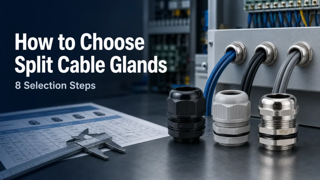
Choose split cable glands correctly by matching cable diameter, connector clearance, mounting, IP rating, material, environment, and approvals.
Lire la suite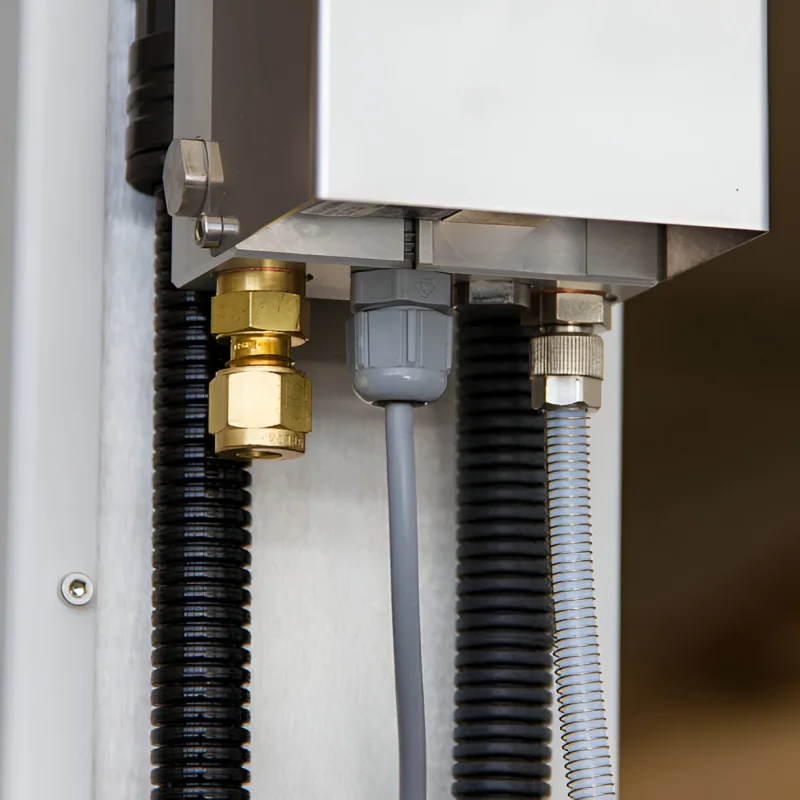
Découvrez les presse-étoupes divisés étanches avec des classements IP66 IP68 en nylon, laiton et acier inoxydable, idéaux pour les installations de câbles préterminés et les réaménagements.
Lire la suite
If you ever typed “are cable glands waterproof” into Google, you not alone. It one of those procurement-and-engineering questions that sounds simple, but it hides a bigger issue: “waterproof” is not a precise engineering specification. In real projects—outdoor telecom cabinets, marine sensors, washdown food lines, rooftop PV combiner boxes—what you really need is a cable […]
Lire la suite