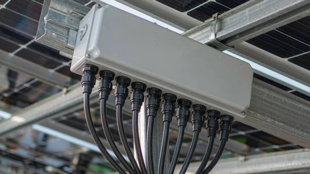
Choosing a cable gland for a combiner box is not difficult in itself. Choosing ten of them, in a row, on the bottom face of a moulded enclosure that is 300 mm wide, is a different task — and it is the one that actually decides whether the box is buildable, serviceable and still sealed in year five.
The failure pattern on combiner boxes is consistent. The glands are ordered last, after the fuses, the isolator and the surge protection have taken the space inside. They arrive in one size because that is the size the string cable uses. They are fitted at whatever pitch the holes allow, and the last two are tightened by feel because a spanner will not fit between them. Six months later the box has water in it and nobody can say which entry let it in.
Everything below is about avoiding that sequence, starting before any part number is chosen.
Count the Entries Before Choosing Any Gland
The count is always higher than the number of strings. A combiner box has string inputs, a DC output, and then the entries nobody schedules: a monitoring or communication cable, a surge protection earth conductor, a heater or thermostat supply where the site is cold, and a spare position for the string that gets added in phase two.
Each of those has a different cable diameter and therefore a different gland size. A box with twelve strings and a single size of gland will usually have at least two sizes fitted by the end of commissioning, which is fine — provided the hole schedule was planned for it. It is not fine when the holes were drilled first and the extra cable had to be squeezed through a string gland with the insert removed.
Entry type
Typical cable
What the gland has to do
String input
4 or 6 mm² PV cable, single core pair
Seal on a hard jacket, hold against pull, resist UV
DC output
Larger submain, often two cores
Strain relief and a wider clamping range
Monitoring / communication
Small signal cable, often 4–8 mm
Seal without crushing; a small insert in a small body
Earth conductor
Bare or green-yellow, single core
Seal around an irregular section, or use a dedicated earth entry
Spare position
None at installation
Must be sealed now with a blind plug and openable later
The Entry Schedule
An entry schedule is one page and it prevents most of the rework. It is drawn as the bottom face of the box, to scale, with every hole positioned, sized and labelled. If the schedule cannot be drawn without glands touching, the box is too small for the string count and no gland selection will fix it.
Column
What goes in it
Why it matters later
Entry number
Matching the label inside the lid
Fault-finding without tracing cables
Cable and measured diameter
From the cable datasheet, not the conductor size
Sets the gland size and proves the range was respected
Gland size and thread
M20, M25, PG13.5 and so on
Matches the punch or knockout used
Hole diameter and tolerance
The drilling or punching dimension
Prevents an oversized hole that no washer will seal
Position on the face
X and Y from a datum edge
Keeps spanner clearance and stops clashes
Spare or used
Blind plug or gland fitted
Tells the next technician what is available
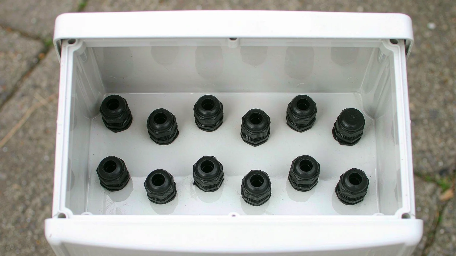
Two offset rows rather than one continuous line: every gland keeps clear space for a spanner, and the spare positions stay plugged.
Spacing: the Dimension Nobody Draws
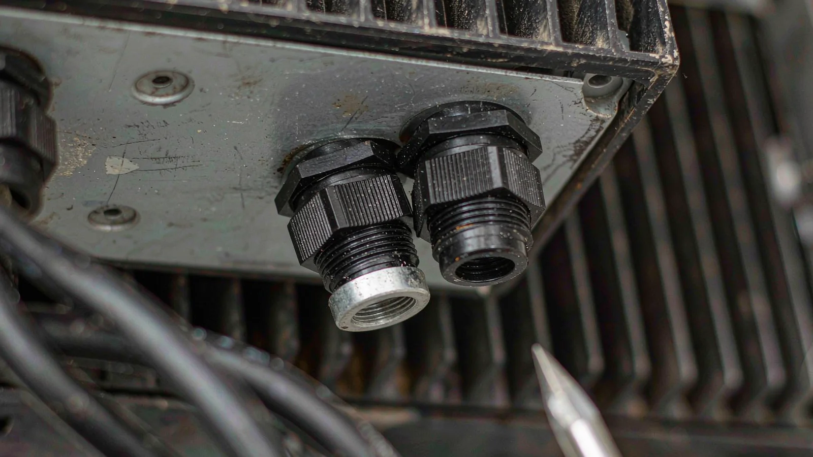
A gland needs room to be tightened, and that room is set by the spanner across the body and the dome nut, not by the thread diameter. Two M25 glands whose centres are one thread apart will both fit the holes and neither will be tightenable — the second one will be tightened with pliers or left hand-tight, and hand-tight is where the leak starts.
The working rule is to leave clear space on each side of every gland equal to its spanner size, measured at the widest point of the body. On a crowded box that usually means two rows, offset from each other, rather than one continuous line. An offset pattern also improves access for a socket and gives the cables a natural route into the box without crossing each other.
Two further constraints are easy to forget. The first is the enclosure wall: a hole placed too close to a moulded corner or a rib cannot be sealed because the face is no longer flat under the washer. The second is the door or lid: a gland that protrudes into the swing of a hinged cover will foul it, and the usual field remedy — shortening the gland by leaving the dome nut loose — is not a remedy.
Both holes fit; neither gland can be reached with a spanner at this pitch. The one on the left is also not square in its hole.
Knockouts vs Drilled Holes
Moulded combiner boxes often ship with knockouts or pre-scored positions on the bottom face. They are convenient and they are also a common source of leaks, because a knockout removes material in a step and leaves a rim that is not always flat.
Method
Advantage
Risk to the seal
Moulded knockout
Fast, correct size, no swarf inside the box
Rim may be proud or slightly oval; the washer bridges the step
Hole saw
Any position and size
Swarf and burrs on the sealing face; heat can distort thin plastic
Step drill
Clean edge in thin sheet
Oversize holes if the next step is used for convenience
Punch
Flat face, accurate diameter
Requires access to both sides of the wall
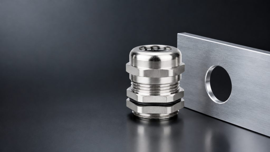
Whichever method is used, the sealing face is what matters: flat, burr-free, and large enough for the washer to sit wholly on it. A deburring tool and thirty seconds per hole is the cheapest reliability measure on the whole box. Where a knockout leaves a raised rim, a sealing washer with a larger outside diameter than the rim is the correct answer rather than extra torque.
Thin Walls and Torque
A moulded box wall is thin, and a gland tightened into it pulls the wall into a cone. The washer follows the cone, the contact area reduces to a ring, and the joint either leaks immediately or leaks after the first thermal cycle. On a metal box the same torque is absorbed by a stiff wall; on plastic it is not.
Three measures work. Use a body with a large washer face so the load is spread over more material. Support the inside of the wall with a reinforcing plate or a gland plate where several entries are close together. And specify a torque that the wall can take rather than a torque the gland can take — the gland’s figure is a maximum, not a target. Where the wall cannot take any meaningful torque, the sealing element has to do the work through compliance rather than through pressure.
Sealing Many Cables at Once
Density creates a second-order problem: several cables in the same box heat each other, and the internal temperature of a combiner box in sun is well above ambient. Elastomer seals in that environment age faster, and the box’s own internal temperature becomes a selection input rather than a detail.
For the entries themselves, four practices make a difference. Size each gland to its own cable rather than to the largest cable in the box. Use blind plugs on spare positions, rated for the same IP as the glands, rather than leaving open holes. Where a single entry must carry two cables, use a purpose-made multi-entry or split gland instead of removing the insert from a standard one. And keep the insert in its gland: an insert that has been removed to pass a connector is a sealing element that will not go back correctly.
Isolation and Fusing: What the Gland Does Not Do
A combiner box contains fuses, an isolator and surge protection, and none of those functions is affected by the gland. It is worth stating because gland selection is sometimes used to solve an electrical problem it cannot solve: a metal gland does not provide DC isolation, and a plastic gland does not improve it.
Where the box is non-metallic and the requirement is to avoid a conductive path through the enclosure, a polyamide gland is the consistent choice, because it introduces no galvanic couple and no metal-to-metal contact with the wall. Where the box is metal and earthed, a metal gland with a proper earth path is consistent — and the earthing question is the one covered in the earthing and bonding guide, not something a plastic gland can substitute for.
Commissioning and Serviceability
A combiner box is re-entered more often than most enclosures: strings are added, fuses are replaced, monitoring is retrofitted. Every re-entry is a chance to damage a seal, so the design should assume the box will be opened.
The entries upstream of the box follow a different logic — UV, jacket hardness and thermal cycling at the module end — which is set out in the solar cable gland selection guide.
Three things make that cheap. Label both the entry and the cable so the right gland can be identified without tracing. Leave at least one plugged spare position per row, so a new string does not require drilling a hole in a live box. And record the gland sizes on the entry schedule inside the lid, so the next technician fits the same part rather than the nearest one in the van.
When a box does leak, the diagnosis is a separate exercise: reading the water to find which entry failed is faster than replacing glands at random, and on a box with twelve entries that difference is most of the labour.
Questions From Combiner Box Builders
Can I use one gland size for every entry?
Only if every cable is within that gland’s range, which is rare once monitoring and earth conductors are counted. Two or three sizes is normal and simplifies spares.
Do I need IP68 glands on an outdoor combiner box?
Usually not. IP65 or IP66 covers rain and hose spray, which is the real exposure. IP68 is relevant where the box can actually be submerged or jet-washed at close range.
Can I drill extra holes after commissioning?
Yes, if the face is flat where you drill, the hole is the correct size, and the inside of the box is protected from swarf. Drilling a live DC box is a separate safety question and usually means isolating the string first.
Why do the glands on the bottom row leak first?
Because the bottom face collects water, and because those entries are the hardest to reach with a spanner. Access difficulty and leak rate correlate strongly on dense boxes.
Should spare entries be plugged or left with a gland fitted?
Plug them. A blind plug is cheaper, sealed to the same rating, and leaves the position clean for the gland that will eventually be needed.
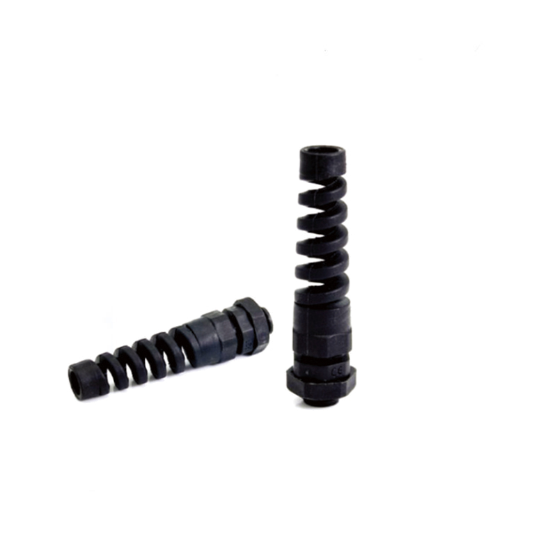
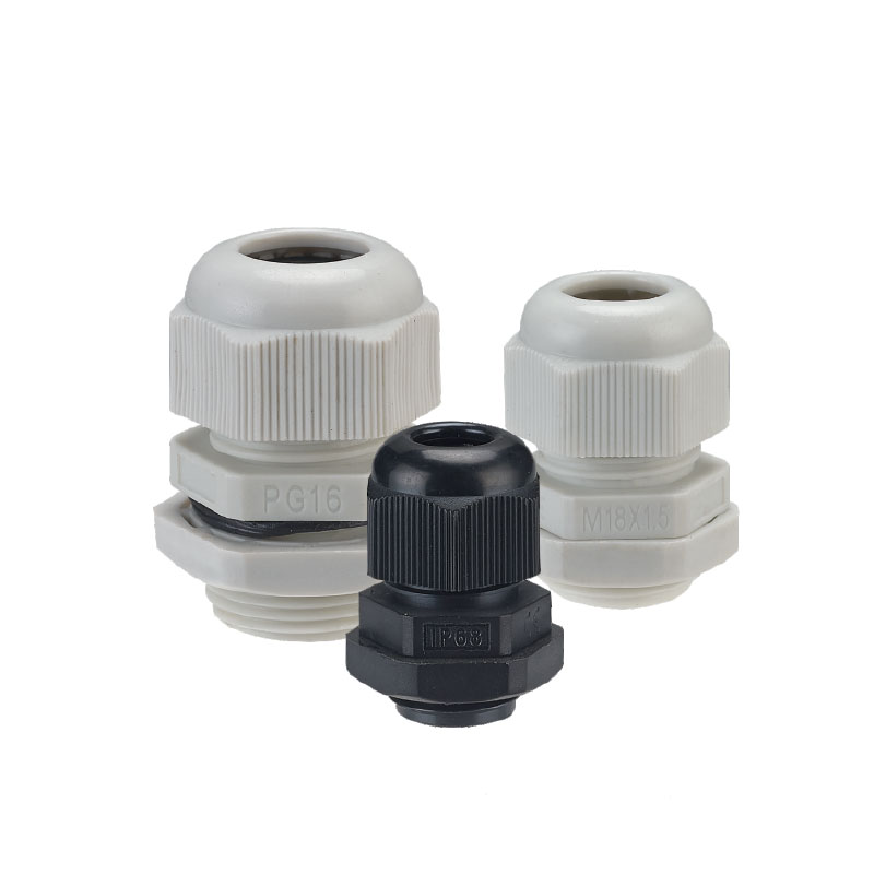
Send the string count, the cable list and the box drawing, and we will produce an entry schedule with gland sizes, hole dimensions and a spacing check before anything is drilled. The polyamide range covers the black UV-stabilised sizes used on moulded boxes, and the hole size chart gives the drilling dimension for each thread.
Quando se trata de garantir a segurança, a durabilidade e a eficiência das instalações elétricas, o humilde prensa-cabo desempenha um papel fundamental. Quer você trabalhe com automação industrial, petróleo e gás, telecomunicações ou energia renovável, a escolha do prensa-cabo correto pode fazer toda a diferença no desempenho e na longevidade de seus sistemas. Neste artigo, exploraremos [...]
Os prensa-cabos à prova d'água desempenham um papel indispensável nos modernos equipamentos elétricos industriais e comerciais. Eles não apenas protegem as entradas de cabos contra poeira e umidade, mas também garantem a segurança do equipamento e prolongam a vida útil. A escolha da classificação IP correta para um prensa-cabo à prova d'água pode evitar efetivamente falhas elétricas ou incidentes de segurança causados por ambientes adversos. [...]
Usamos cookies para aprimorar sua experiência de navegação, veicular anúncios ou conteúdos personalizados e analisar nosso tráfego. Ao clicar em "Aceitar tudo", você concorda com o nosso uso de cookies.