Prensa-cabos à prova d'água
How to Choose Split Cable Glands: 8 Selection Steps
Choose split cable glands correctly by matching cable diameter, connector clearance, mounting, IP rating, material, environment, and approvals.
Leia mais
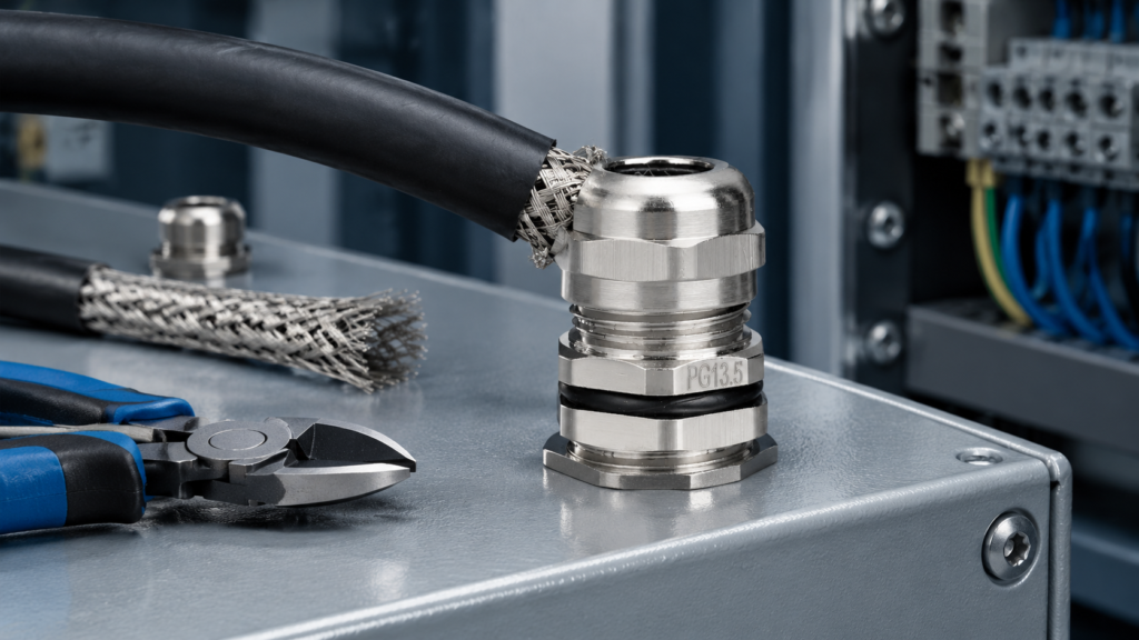
Prensa-cabo EMC installation is a standard gland installation with one extra step that decides whether the fitting does anything: the cable screen has to be bonded to the gland body, and the gland has to be bonded to the enclosure. Get the sealing right and skip the bonding, and you have paid for shielded hardware that performs like a plain gland.
This is the field procedure — what to prepare, the eight steps in order, how to check the bond with an instrument instead of by eye, and the six faults that account for almost every failed EMC termination.
Have these ready before you open the panel. A rework on a live cabinet costs far more than the two minutes of preparation.
If this is your first time fitting a metal gland, work through the general step-by-step waterproof cable gland installation first — the sealing sequence is identical, and this article only covers what the EMC version adds.
There is no universal torque figure that suits every gland size and material — the setting comes from the gland’s own datasheet. What you can control is what each setting is meant to achieve, which is the part that actually prevents rework.
| Setting | Governed by | What a correct result looks like |
|---|---|---|
| Screen exposure length | The gland’s stated strip dimension | Braid reaches the contact ring with no bunching and no exposed screen beyond the gland |
| Cap nut torque | The gland’s specified figure for that size and material | Contact ring closed evenly around the circumference, braid undeformed |
| Body / locknut torque | Enclosure wall thickness and thread size | Continuous metal-to-metal contact with the panel — no paint or washer in the electrical path |
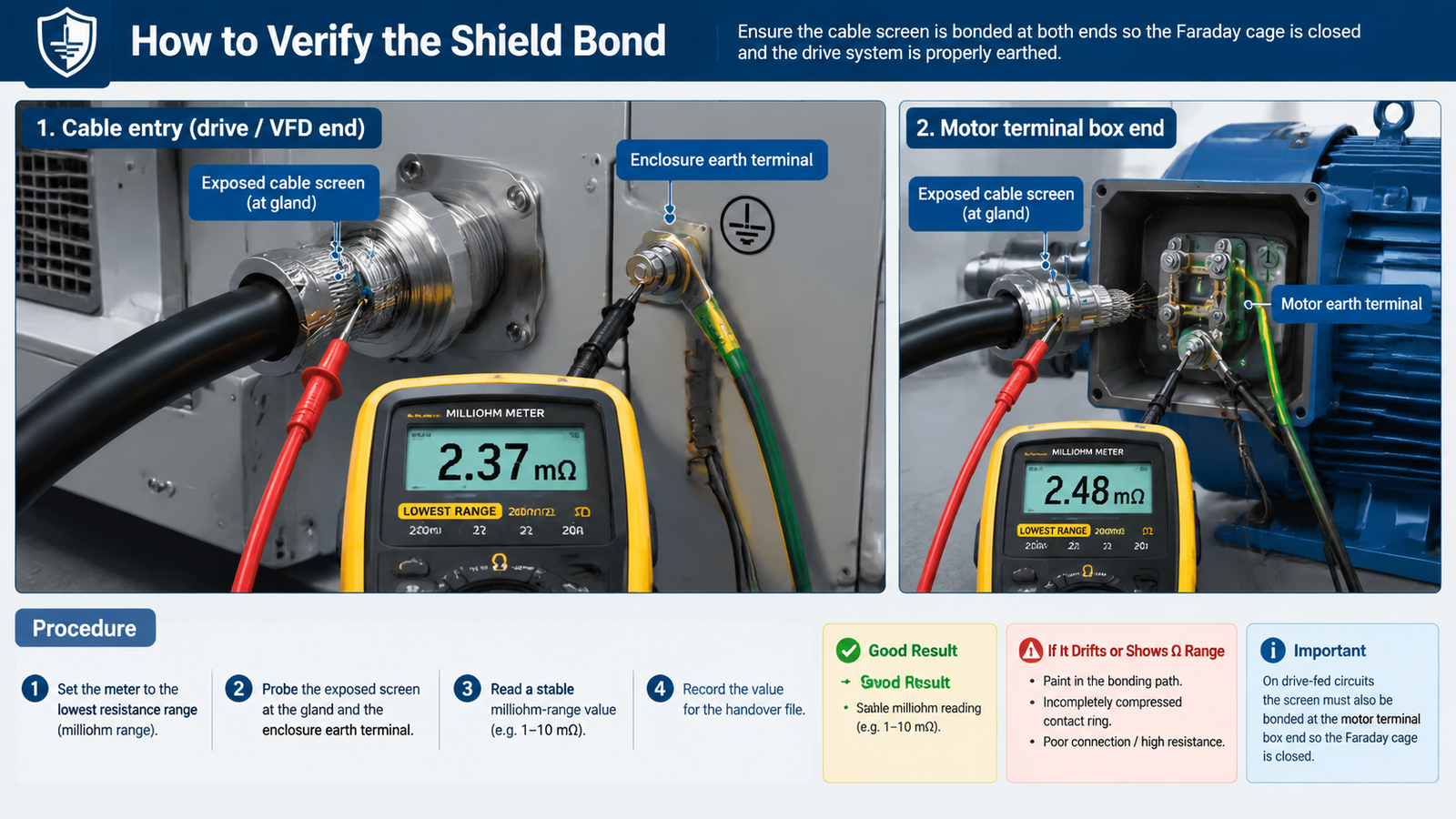
| Screen-to-enclosure resistance | Measured after assembly | A stable milliohm-range reading; a drifting or ohm-range reading means an isolating layer or a loose joint |
Under-tightening leaves a high-resistance contact that may pass a bench check and fail in service under vibration. Over-tightening crushes the braid and cuts the contact surface into the strands, which reduces the effective contact area rather than improving it.
A visual check cannot tell you whether a screen is bonded. Measure it.
For a deeper look at why the entry point is where shielding usually fails, see what an EMC cable gland is and how it works.
| Symptom | Likely cause | Fix |
|---|---|---|
| Encoder or communication faults that appear only when the drive ramps | Screen not bonded at the entry — floating screen or a pigtail drain wire | Re-terminate with a 360° contact ring; remove the pigtail |
| No improvement after fitting EMC glands throughout | Gland isolated by a painted or insulated panel face | Fit an earth tag or locknut, or mask the bonding surface to bare metal |
| Water inside the enclosure after washdown | Cable OD at the extreme of the clamping range, or cap nut under-torqued | Re-measure the cable and re-size the gland; re-torque to specification |
| Braid cut or frayed at the entry | Over-tightened cap nut, or the shield was scored while stripping | Shorten the strip, redo the fold-over, torque to the specified figure |
| Good continuity reading, interference unchanged | Screen bonded at one end only | Bond the motor terminal box end as well |
| Gland works loose over months of operation | No locknut, or vibration loosening a joint set at the wrong torque | Add a locknut, re-torque, re-check continuity at the next service |
O wider installation precautions for waterproof glands cover the sealing side of the same job — cable support, bend radius and gland orientation.
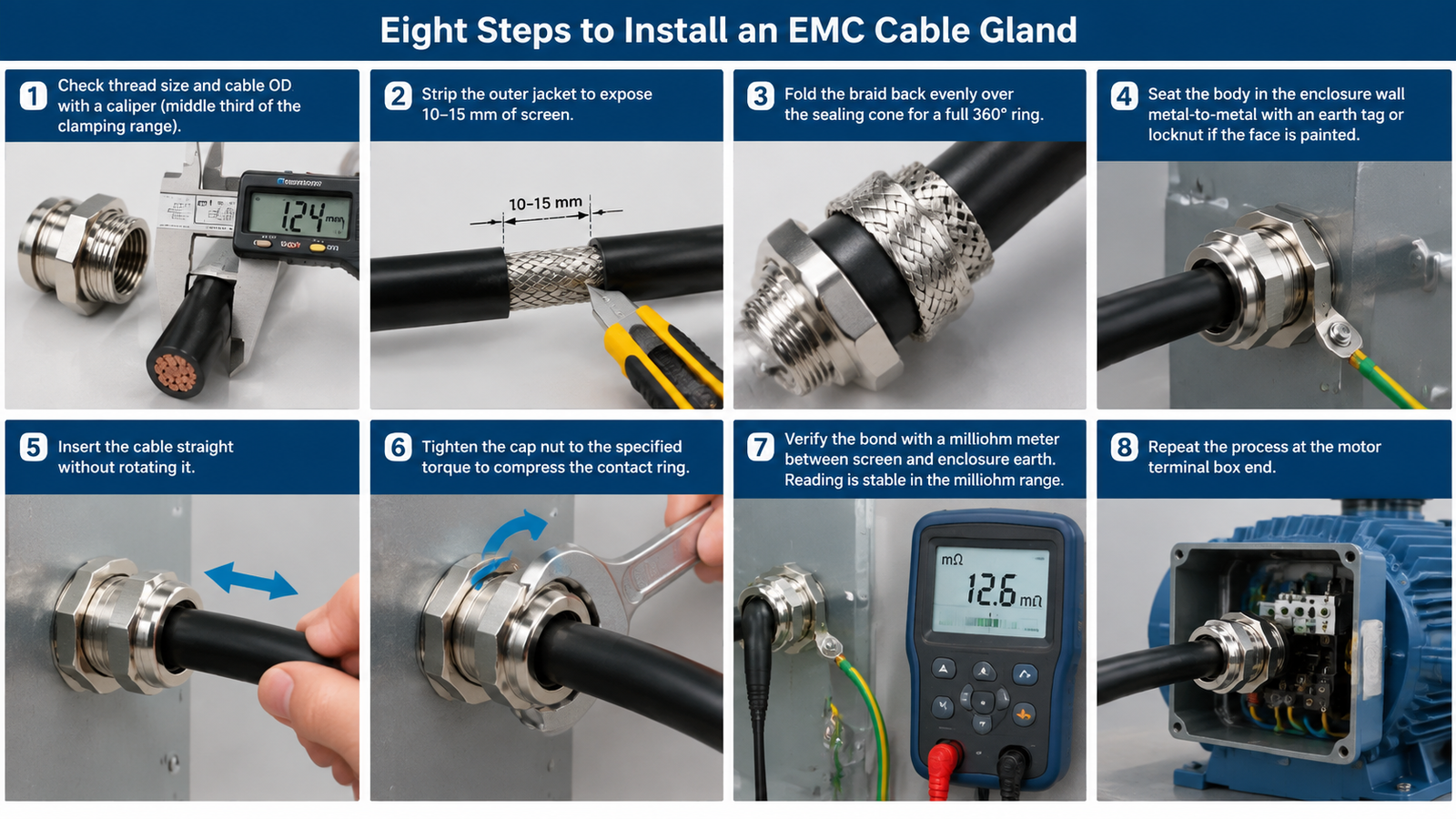
EMC cable gland installation is where an EMC gland either works or becomes an expensive standard gland. The sequence is short: measure the cable and confirm the thread, expose and fold the screen evenly, bond the body to bare metal, compress the contact ring to the specified torque, then measure the screen-to-enclosure resistance and write the number down. Do the same at the far end of the cable.
Everything that fails in the field fails at one of those points — an isolating layer of paint, a bunched braid, an over-tightened cap nut, or a bond at one end only. None of them are visible on a walk-through. All of them show up on a meter, which is why the continuity check is not optional.
Not sure which gland suits a given circuit, or need the torque figure for a specific size? Send us the cable list and thread standard, and our engineering team will return the correct gland selection, the torque data and an FOB quotation within one working day — contact us here.
Strip the jacket to expose the screen, fold the braid evenly over the sealing cone, seat the body in bare metal on the enclosure, insert the cable, then tighten the cap nut to the specified torque so the contact ring closes around the full circumference. Finish by measuring continuity between the screen and the enclosure earth.
To the figure stated for that gland size and material — there is no universal torque value. Tight enough to close the contact ring evenly around the circumference, not so tight that the braid is crushed or cut. If the gland came without a figure, ask the supplier for the torque data rather than estimating.
Measure the resistance between the exposed screen at the gland and the enclosure earth terminal with a milliohm meter or bonding tester. A stable milliohm-range reading indicates a bonded screen; a drifting or ohm-range reading points to paint in the path or an incompletely compressed contact ring.
No exotic tooling — a stripper, caliper, correct spanner or driver and a torque wrench. The one instrument people omit is the milliohm meter or bonding tester, and without it there is no way to prove the shield termination is electrically real.
Yes, provided the cable is shielded and there is enough slack to re-strip and re-terminate the screen. Retrofit is common on panels that were built with standard glands on drive and encoder cables. Confirm the cable’s actual OD, and re-check the enclosure bonding path while the panel is open.
Choose split cable glands correctly by matching cable diameter, connector clearance, mounting, IP rating, material, environment, and approvals.
Leia mais
Os prensa-cabos à prova d'água desempenham um papel fundamental nas indústrias modernas, especialmente no setor B2B. Eles não apenas garantem a vedação das conexões de cabos, evitando a entrada de água e poeira, mas também aumentam a segurança e a estabilidade gerais dos sistemas elétricos. Você sabia que a instalação incorreta de prensa-cabos pode não apenas reduzir a vida útil do equipamento [...]
Leia mais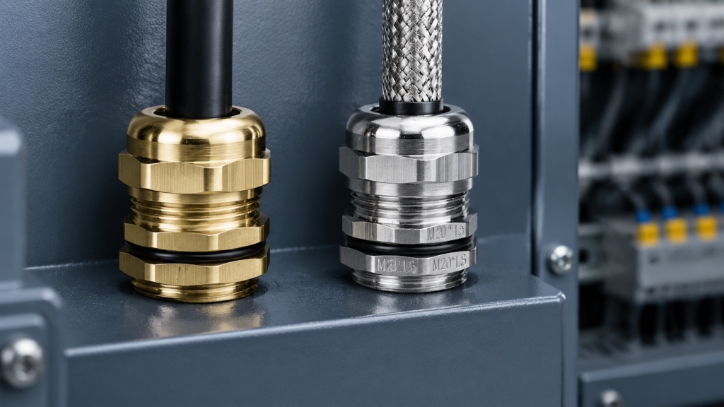
EMC and standard cable glands seal and grip identically; only the screen termination differs. Compare specs, indicative FOB prices, and use a four-check test to decide per circuit.
Leia mais