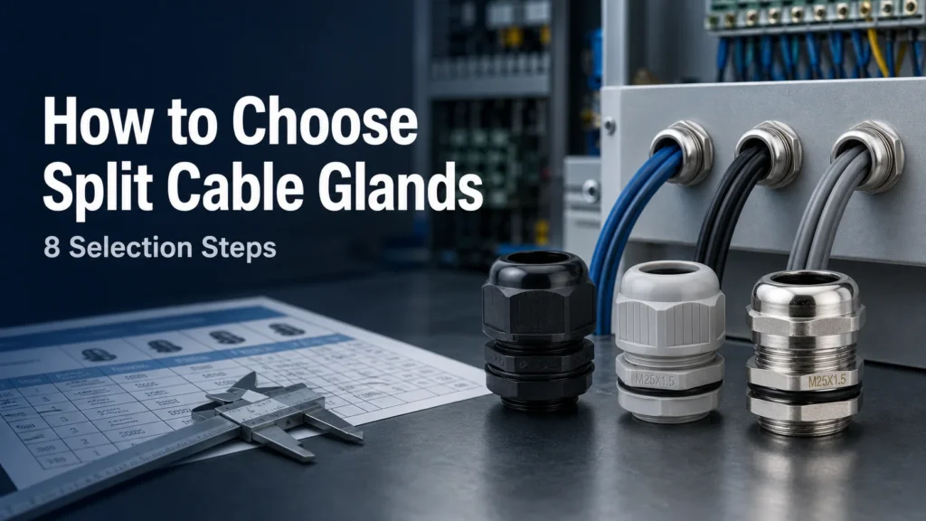
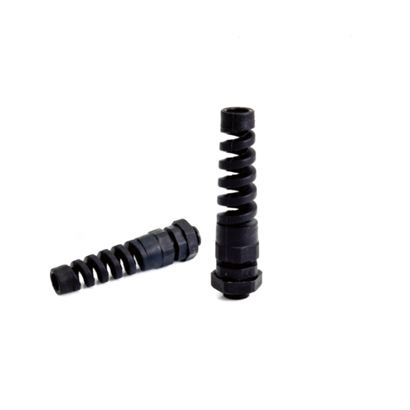
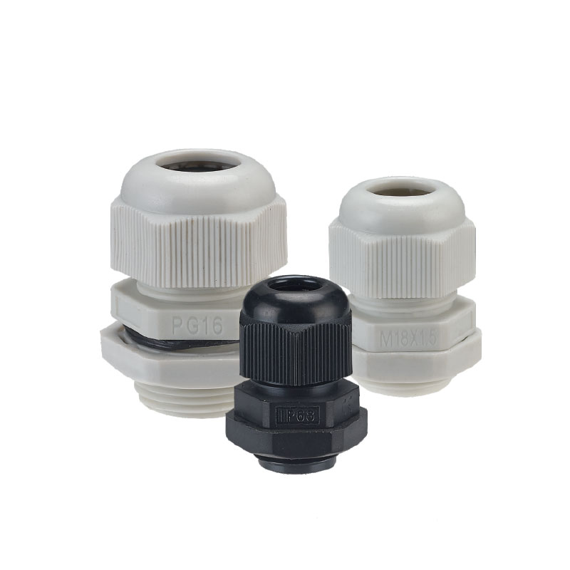
To choose split prensaestopas, start with the cable outside diameter and connector size, then match the sealing range, mounting interface, ingress rating, material, operating environment, strain-relief requirement, and approvals. A split design is especially useful for pre-terminated cables because it installs around the cable without removing an M8/M12, RJ45, USB, HDMI, D-sub, or other factory-fitted connector.
The best gland is not simply the largest model that fits the connector. The connector must pass through the enclosure cut-out, while the split insert must compress correctly around the cable jacket. This guide turns those separate requirements into a practical selection process for control cabinets, machinery, outdoor equipment, marine systems, and retrofit projects.
When Is a Split Cable Gland the Right Choice?
Choose a split cable gland when a cable is already terminated, cannot be disconnected easily, or should retain its factory-tested connector. The two-part body and split sealing insert close around the cable after it has been routed. This avoids cutting, stripping, and re-terminating conductors.
A conventional gland may be more economical when the cable end is accessible and no connector blocks installation. A larger modular cable-entry frame may be better when many connectorized cables must share one cut-out. For a detailed explanation of the construction and use cases, see the waterproof split cable gland guide.
Installation situation
Usually the better option
Razón
One pre-terminated cable
Split cable gland
Compact entry without removing the connector
One unterminated cable
Standard cable gland
Simple construction and broad size availability
Several connectorized cables
Multi-cable split gland or entry frame
Higher cable density through one opening
Armored or EMC cable
Purpose-designed gland
Armor clamping or shield bonding must be documented
Step 1: Record the Cable and Connector Dimensions
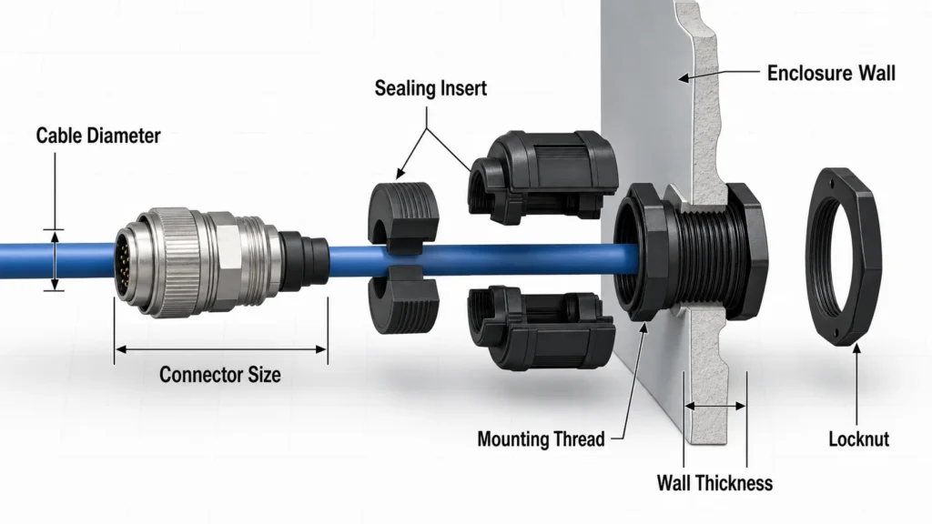
Measure the cable outside diameter on a straight, undamaged section of jacket with a caliper. Do not select the insert from conductor cross-section, nominal cable size, or connector diameter. The sealing insert grips the jacket, so its stated clamping range must include the actual outside diameter.
Next, measure the connector’s largest height and width, including latches, strain-relief boots, and angled backshells. These dimensions determine the minimum cut-out through which the connector can pass. Also record the cable bend radius and the straight length between the connector and the gland position. A gland that fits the cable can still be impossible to assemble if the connector body blocks access.
Step 2: Match the Insert to the Cable
Select a split insert whose clamping range comfortably covers the measured cable diameter. A cable near the center of the range normally gives more tolerance for jacket variation than one at the extreme limit. Never fill a gap with tape, sealant, or an improvised sleeve unless the gland manufacturer explicitly approves that method.
For several cables, verify every insert opening separately. Confirm the allowed diameter for each position and use approved blanking plugs for unused holes. Cables with oval, corrugated, braided, or soft jackets may need a special insert or test because their sealing behavior differs from that of a smooth, round cable.
Step 3: Check the Enclosure Cut-Out and Mounting Method
Split glands may use metric, PG, NPT, or other threads, a locknut, fixing screws, or a snap-in body. Match the gland to the existing cut-out instead of relying only on the product name. Confirm:
cut-out diameter and shape;
thread type, pitch, and usable thread length;
panel thickness and locknut clearance;
space for tools and body assembly;
flat sealing area around the opening;
connector clearance behind and in front of the panel.
If the panel has an existing threaded hole, both thread standard and pitch must match. If the gland passes through a plain hole, check that the thread is long enough for the panel, gasket, washer, and locknut. For general product and thread options, review the waterproof cable gland range.
Step 4: Define the Required Ingress Protection
Choose the required IP or enclosure rating from the real exposure: indoor dust, rain, temporary immersion, washdown, or another defined condition. Do not assume that every split gland is IP68. Use the rating documented for the complete combination of body, insert, cable range, gasket, and mounting method.
Ingress protection is a system result. A rated gland cannot compensate for a damaged cable jacket, dirty split line, rough panel surface, wrong insert, missing gasket, or incorrect tightening. For wet or outdoor equipment, ask whether the stated rating was tested in the intended mounting orientation and under conditions relevant to the project.
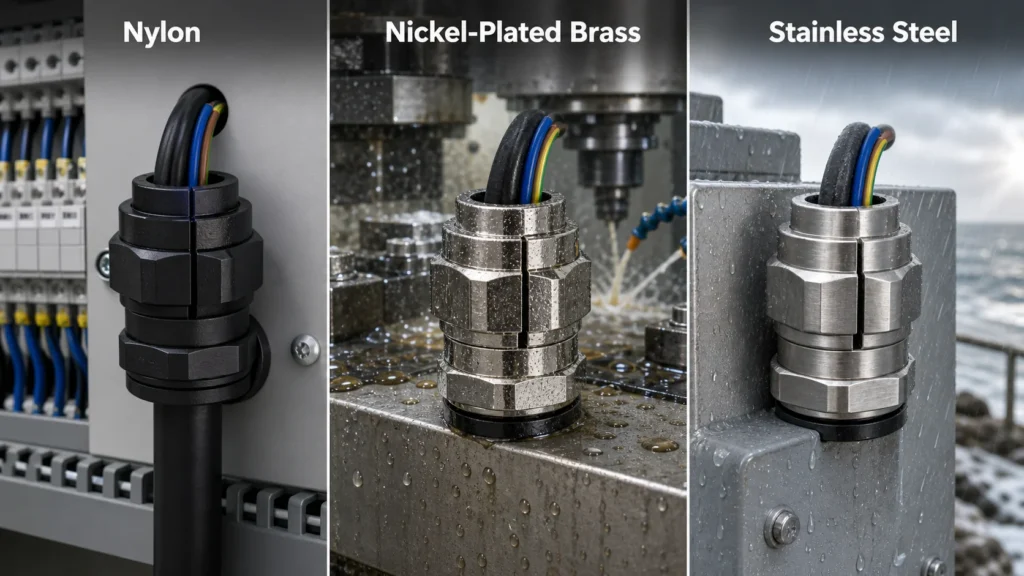
UV stability, temperature range, chemical compatibility, impact strength
Latón niquelado
Strong, durable, conductive, suitable for many industrial environments
Plating suitability, corrosion exposure, grounding or EMC design
Acero inoxidable
High corrosion resistance and mechanical durability
Steel grade, salt or chemical exposure, galvanic compatibility
The sealing insert is just as important as the body. Check its temperature limits and resistance to oil, fuel, coolant, cleaning agents, salt, ozone, and UV exposure. Do not infer chemical compatibility from color or appearance. If the project is mainly cost-sensitive and electrically non-conductive construction is useful, compare the site’s nylon cable gland options. For demanding wet environments, the marine waterproof cable gland guide explains material trade-offs in more detail.
Step 6: Verify Strain Relief and Mechanical Performance
A sealed entry is not automatically a strong cable anchor. Check the manufacturer’s documented pull-out or strain-relief performance if the cable can be pulled, vibrated, moved, or flexed. Confirm whether the rating applies to the exact insert and cable diameter.
Heavy connectors and moving cables may need separate support so their weight and bending moment are not carried by the gland alone. Maintain the cable’s minimum bend radius and provide a straight section at the seal. A tight bend immediately beside the gland can distort the insert and reduce sealing reliability.
Step 7: Confirm Special Electrical and Safety Requirements
A standard split gland should not be treated as an EMC, armored-cable, fire-rated, or hazardous-area gland unless the documentation specifically states that function. Metal construction alone does not create a continuous shield termination, and a waterproof rating does not equal explosion protection.
Before ordering, list every mandatory standard or approval, such as an enclosure rating, UV or flammability requirement, railway or marine approval, or hazardous-location certification. Verify the exact part number and assembly rather than assuming that approval for one product family applies to every insert and accessory.
Step 8: Validate Installation and Maintenance Needs
Review how technicians will assemble, tighten, inspect, and reopen the gland. Check the required tools, tightening torque, fastener access, and whether the insert can be replaced without disturbing adjacent cables. For maintenance-heavy equipment, reusable inserts and captive fasteners may justify a higher initial cost.
Ask for installation instructions before the production order. A small pilot installation can reveal connector-clearance, panel-thickness, and cable-tolerance problems that drawings alone may miss.
Split Cable Gland Selection Checklist
Item to provide
Why the supplier needs it
Cable outside diameter and jacket material
Selects the insert size and checks compatibility
Connector maximum dimensions
Confirms cut-out and assembly clearance
Number of cables
Determines single, multi-hole, or frame design
Cut-out, thread, and panel thickness
Matches the mounting interface
Required IP or enclosure rating
Defines sealing performance
Temperature and exposure conditions
Guides body and seal material selection
Pull, vibration, and flexing loads
Defines strain-relief and support needs
Required approvals
Prevents an unsuitable compliance substitution
Common Selection Mistakes
Sizing from the connector only: the connector controls pass-through clearance, but the cable diameter controls the seal.
Choosing by thread name alone: pitch, panel thickness, cut-out, and locknut space also matter.
Assuming “split” means waterproof: require a documented rating for the complete assembly.
Ignoring the cable jacket: soft, oval, damaged, or chemically incompatible jackets may not seal reliably.
Overlooking bend radius: a connector may fit through the hole but still lack installation space.
Using a standard model for EMC or hazardous areas: these functions require purpose-designed, approved products.
Preguntas frecuentes
How do I size a split cable gland?
Match the split insert’s clamping range to the measured cable outside diameter. Separately confirm that the connector passes through the enclosure cut-out and that the gland mounting dimensions fit the panel.
Can I use a split cable gland for an RJ45 or M12 cable?
Yes, if the cable diameter fits an approved insert and the connector has enough pass-through and assembly clearance. Split glands are commonly selected specifically to preserve factory-terminated connectors.
Are split cable glands IP68?
Some are, but not all. Verify the tested rating for the exact gland body, insert, cable range, gasket, and installation arrangement.
Can a split cable gland hold multiple cables?
Only models designed with multi-hole or modular inserts can do so. Each cable must fit its specified opening, and unused positions need approved blanks.
Should I choose nylon, brass, or stainless steel?
Choose nylon for lightweight, insulating, cost-effective installations; brass for robust general industrial use; and suitable stainless steel for severe corrosion or hygiene requirements. Always confirm temperature, chemical, UV, and certification needs.
What details should I include in an RFQ?
Send cable and connector dimensions, cable count, panel cut-out and thickness, thread standard, ingress rating, materials, environmental exposures, strain-relief needs, order quantity, and required certifications. Photos or dimensioned drawings can reduce selection errors.
Final Recommendation
The correct split cable gland is chosen by matching two paths: the connector must pass through the enclosure, and the insert must seal around the cable jacket. After that, verify mounting, ingress protection, material compatibility, mechanical loads, and approvals. This method prevents the most common failures: an insert that cannot seal, a connector that cannot be routed, or a gland that does not meet the operating environment.
¿Alguna vez se ha preguntado cómo esos pequeños dispositivos aparentemente insignificantes garantizan que los cables permanezcan seguros y fiables en entornos húmedos o difíciles? Este es el secreto del prensaestopas estanco. Actuando como "guardián" de los cables que entran y salen de los equipos, no sólo consigue una conexión segura, sino que también protege los cables de la humedad, el polvo y [...].
¿Alguna vez se ha preguntado si un prensaestopas estanco puede satisfacer las exigencias de un entorno a prueba de explosiones? Es una pregunta habitual que se hacen muchos profesionales que trabajan en entornos industriales. Con el aumento de las normativas de seguridad y las diversas necesidades de las aplicaciones, es fundamental comprender la diferencia y la compatibilidad entre los prensaestopas estancos y los prensaestopas antideflagrantes. Ambos tipos de [...]
A brass waterproof cable gland helps protect cable entries from water, dust, and strain in industrial and marine installations. Learn how to choose the right model, size, and supplier.
Utilizamos cookies para mejorar su experiencia de navegación, publicar anuncios o contenidos personalizados y analizar nuestro tráfico. Al hacer clic en "Aceptar todo", aceptas el uso que hacemos de las cookies.