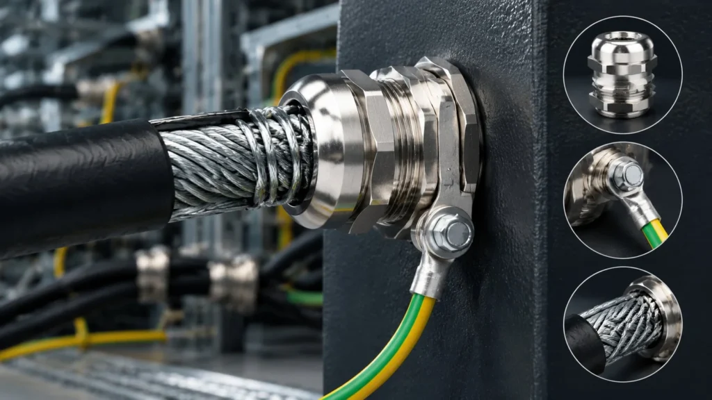
Ask an installer whether the armoured cable gland is earthed and you will get a confident yes. Ask how they know the armour satisfies the disconnection time, and the answer usually stops at “the tag is on and it reads low on a multimeter”. Those are two different questions, and only the first one has been answered.
This guide deals with the earthing of the armour specifically: what hardware completes the connection, where the resistance actually accumulates, whether the armour is permitted to act as the circuit protective conductor at all, and how to interpret the test result you write on the sheet. The general theory of earthing and bonding — including how it differs from EMC bonding — is covered in the cable gland earthing guide.
The gland makes the connection; the cable decides whether it is adequate
An armoured gland does one electrical job: it terminates the armour to the enclosure. That connection can be perfectly made and still be inadequate, because adequacy is a property of the armour cross-section and the fault current, not of the gland.
This is the distinction that separates a passing installation from a compliant one. The gland contributes a low-resistance joint; the cable determines whether that joint can carry the fault current for the time the device takes to operate.
Three hardware routes to armour continuity
The armour is clamped by the gland, but the current still has to get from the gland body into the enclosure’s earth system. There are three routes, and they are not interchangeable across enclosure types.
Route
Where it fits
Strength
Weak point
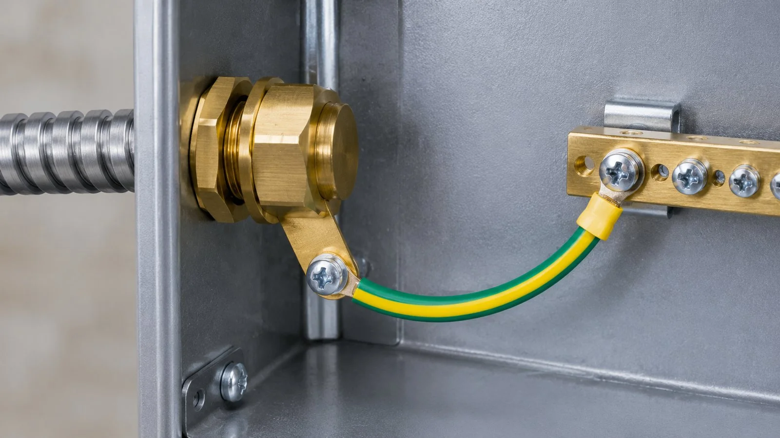
Earth tag (banjo) under the locknut
General industrial enclosures with an internal earth bar
Visible, replaceable, accepts a fly lead of any practical size
Only contacts through the locknut and thread face; paint or a nylon washer in the stack breaks it
Integral earthing nut
Glands supplied with an earthing nut in place of the standard locknut
One component instead of three; less assembly-dependent
Fixed lead size; the nut must match the thread form
Dedicated earth boss or screw on the gland body
Ex-rated and heavier armoured glands
Direct metal-to-metal contact on the body; specified in the certificate
Part of the certified configuration — an added tag does not substitute for it
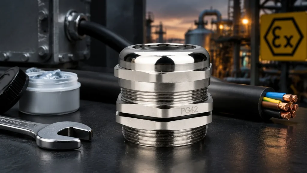
On a hazardous-area installation the third route is not an option to be improved on. If the gland certificate specifies an earth boss, that is the bonding point, and moving the connection elsewhere departs from the tested configuration.
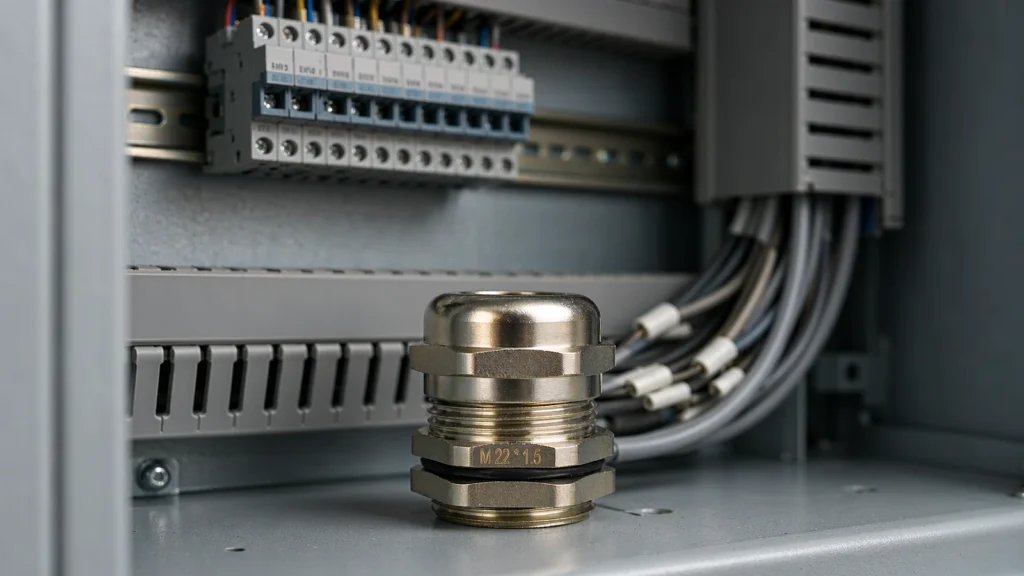
A brass gland entering a metal enclosure, with the earth tag clamped under the locknut inside and a short earth lead taken to the internal earth bar.
Contact resistance is a stack, not a point
When an armour continuity reading is high, the instinct is to blame the tag. In practice the resistance is the sum of several interfaces, and the tag is rarely the largest term.
Interface
What goes wrong over time
What to look at
Wire to cone and clamping ring
Wires not fully seated, corrosion under the clamp, a wire cut through
Even wire distribution, no bright-cut strands, no white or rust-coloured deposits
Clamp to gland body
Thread contamination, partial engagement, body not fully closed
Body seated against its stop, thread clean, no sealant in the joint
Body thread to enclosure
Paint or powder coat in the thread, insulating washer, loose locknut
Bare metal at the contact face, washer type permitted by the gland
Tag to locknut and wall
Tag fitted outside the locknut, oxidised contact face, tag painted
Tag position in the stack, contact faces cleaned
Fly lead and lug
Undersized lead, loose lug, corrosion at the bar
Lead cross-section, crimp quality, torque at the bar
Because these are in series, one bad interface dominates the reading and hides the rest. Inspect the stack before measuring, and measure at the bar rather than at the gland body.
Is the armour allowed to be the CPC?
In many installations the steel wire armour is used as the circuit protective conductor. It is permitted only when its cross-section is adequate for the fault current and disconnection time, and that check is arithmetic, not a judgement call.
Paso
What you need
Where it comes from
1. Fault current
Prospective earth fault current at the point of the fault
Installation design, supply data, or measured loop impedance
2. Disconnection time
Time the protective device takes at that current
Device time-current curve
3. Material factor k
Factor for the conductor material and its initial and final temperature
Your wiring regulation’s table — commonly cited values are around 143 for copper and around 46 for steel armour, but use the table your standard edition publishes
4. Adiabatic check
S ≥ √(I²t) / k, using the armour’s actual cross-section
Calculated
5. Verdict
Armour adequate, or a separate CPC core required
Design decision recorded on the drawing
The consequence surprises people: steel has a much lower k than copper, and the armour is usually far smaller than the phase conductor. A cable that looks generously armoured often fails the check, and the correct answer is a separate CPC core bonded at both ends rather than a thicker gland.
Two rules follow. The armour is a conductor, so it is bonded at both ends — the single-end rule belongs to shields, as explained in the SWA gland guide. And no choice of gland makes an inadequate armour adequate.
Earth tag, earthing nut or boss: choosing by enclosure
Selection is driven by what the enclosure offers and what the certificate says, in that order.
Sheet-steel enclosures with an internal earth bar. Tag under the locknut plus a short fly lead to the bar. Simple, inspectable, and the default for most industrial panels.
Cast or machined enclosures with a designated bonding point. Use the point. A tag on the entry thread may be outside the intended current path.
Ex-rated glands. Follow the certificate. Adding a tag to a gland with an earth boss does not improve the bonding and may interfere with a sealed entry.
Plastic enclosures. There is no enclosure earth path; the armour bond has to be taken out through a metal gland plate or an internal bonding stud connected to the system earth. A tag alone bonds the gland to nothing.
Whatever the route, the mechanical assembly must respect the entry: the sequence at the enclosure face is in the SWA gland installation guide.
Fly lead sizing and routing
The fly lead is a conductor in the fault path and is sized as one. Two habits cause most problems: a lead smaller than the CPC requirement, and a lead routed long and loose so its impedance — not the armour’s — becomes the limiting term.
Size the lead to at least the CPC requirement, and check the local minimum where the armour is the CPC.
Keep it short and direct, with a crimped lug at each end.
Terminate on the earth bar, not on a random enclosure screw.
Identify it as a protective conductor along its length.
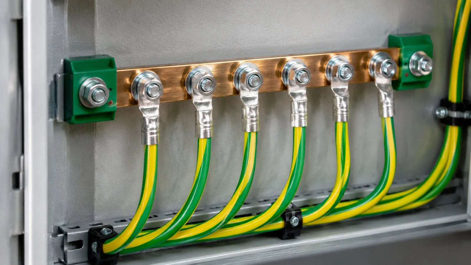
Where several glands share an enclosure, each needs its own connection to the bar. Daisy-chaining fly leads puts one circuit’s fault current through another circuit’s tags.
Testing: what to measure and what the reading proves
A continuity reading proves a conductive path exists. It does not prove the path can carry fault current, nor that disconnection times will be met.
Measure at the far end. From the armour at the gland to the earth bar, not body to tag — the interesting term is the whole stack.
Use a low-resistance instrument. A multimeter is adequate for go/no-go and poor for recording a value; four-wire measurement removes lead resistance.
Measure before and after cleaning. A reading that halves after brushing a contact face shows the interface is the problem, not the cable.
Record instrument, range and location. A number without these cannot be compared at the next inspection.
Re-test after any maintenance that opened the enclosure or disturbed the gland.
Write the measured resistance on the sheet and check the design against the earth fault loop impedance for that circuit, not against a fixed number in ohms.
Several armoured gland fly leads terminated individually on an enclosure earth bar. Each circuit has its own connection rather than daisy-chaining from gland to gland.
The numbers that are not in any standard
Installation pages often state that armour continuity must be “less than 1 ohm”, or “less than 0.1 ohm”, as if these were acceptance criteria. They are not published limits in IEC 60364 or the UK wiring regulations; they circulate because they are easy to remember.
They also mislead in both directions. A 0.4 Ω reading on a long run can be normal and still satisfy the loop impedance requirement; a 0.05 Ω reading on a joint about to corrode open proves nothing about next year. What matters is whether the total earth fault loop impedance lets the device operate within the permitted disconnection time — calculated from the circuit, not read off the gland.
Practical acceptance therefore has three parts: a low and stable measured resistance at the termination, a calculated loop impedance that meets the disconnection requirement, and a record showing both were checked. Where the armour is also the CPC, add the adiabatic check above.
Corrosion, paint and the interfaces that fail later
Armour earthing rarely fails on day one. It fails two or three years later, at an interface that was marginal when it was assembled.
Powder coat under the locknut. The coating behaves as an insulator until the nut cuts through it, and the cut is not always clean. Bare the contact face deliberately.
Galvanic couples. A brass tag on a galvanised steel wall, or a prensaestopas de acero inoxidable on an aluminium enclosure, creates a small cell at exactly the contact you depend on. Where the couple is unavoidable, keep water off it and inspect it.
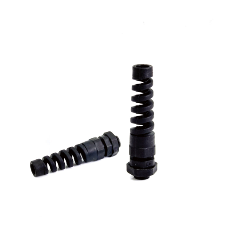
Outdoor entries. Water sitting in the thread and around the tag accelerates both corrosion and loosening. The shroud keeps weather off the gland; it is not a substitute for a dry contact face.
Vibration. A locknut that was tight at commissioning can lose preload, taking the tag contact with it. This is one of the reasons continuity is re-checked after maintenance rather than only at handover.
For enclosures where wall type, gasket line or gland plate determines whether earthing survives, read the entry-side details before ordering. If you need armoured glands supplied with tags, shrouds and earthing nuts as a matched kit, send us the cable schedule and the enclosure type.
Frequently asked questions
Must both ends of an armoured cable be earthed?
Yes, for the armour. It is a conductor providing a fault path, so it is bonded at both ends. The single-end rule applies to shields used for EMC, where a second bond can create a circulating current path — a different function with different rules.
Can the steel wire armour be used as the CPC?
Only if its cross-section passes the adiabatic check for the prospective fault current and disconnection time. Because steel has a low k factor and the armour is usually much smaller than the phase conductor, a separate CPC core is often required.
Is “less than 1 ohm” a valid pass criterion for armour continuity?
No. It is not a published limit in the main installation standards. The design check is whether the earth fault loop impedance lets the protective device operate within the permitted disconnection time; the measured resistance at the termination is a separate workmanship indicator.
Where does the earth tag go — inside or outside the enclosure?
Inside, over the entry thread with the locknut on top of it. Fitting the tag outside the locknut, or between locknut and wall with no clamping force, is the most common reason an armour continuity test fails on a new installation.
Does an earth tag work on a plastic enclosure?
Not on its own. A plastic enclosure offers no earth path, so the armour bond must be taken through a metal gland plate or an internal bonding stud connected to the system earth. The tag only connects the gland to whatever it is bolted to.
A practical guide to installing explosion proof cable glands: barrier compound curing, entry thread engagement, tightening criteria and the inspection record that IEC 60079-14 expects.
A control panel cable gland is usually chosen by hole size and paid for thirty centimetres later at the terminal block. Entry height, bend radius, door routing, shield bonding and the marking that makes a panel traceable.
Zone 1 and Zone 2 cable glands are selected from the area classification, not the catalogue. See how the zone sets the minimum EPL, what the gland marking must show, and the mistakes to avoid.
Utilizamos cookies para mejorar su experiencia de navegación, publicar anuncios o contenidos personalizados y analizar nuestro tráfico. Al hacer clic en "Aceptar todo", aceptas el uso que hacemos de las cookies.