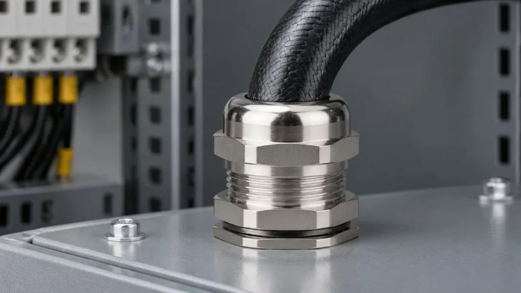
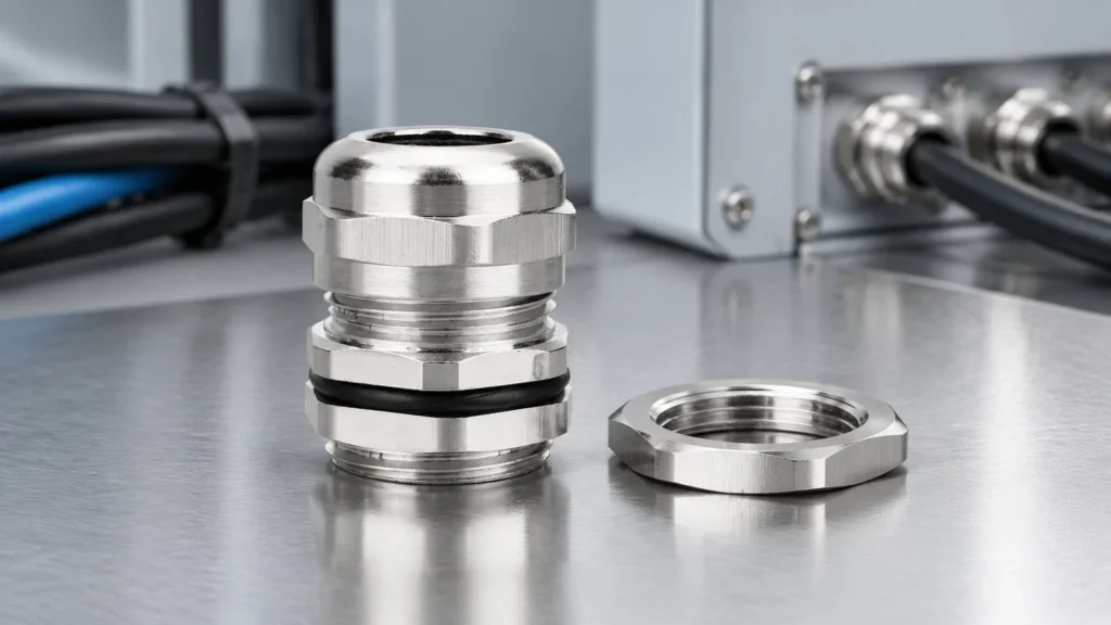
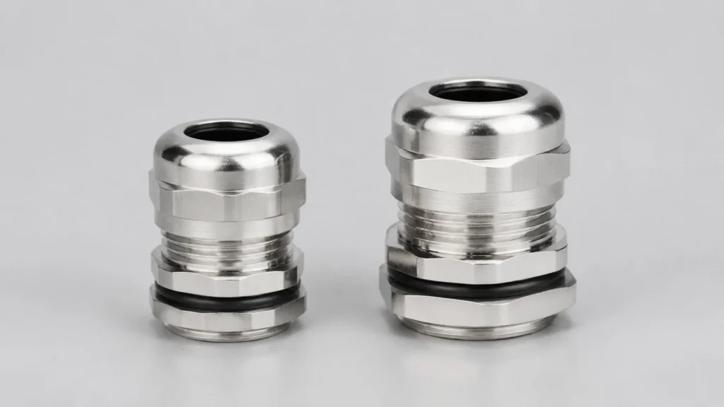
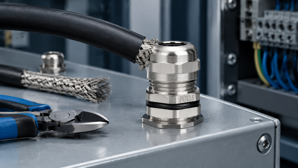
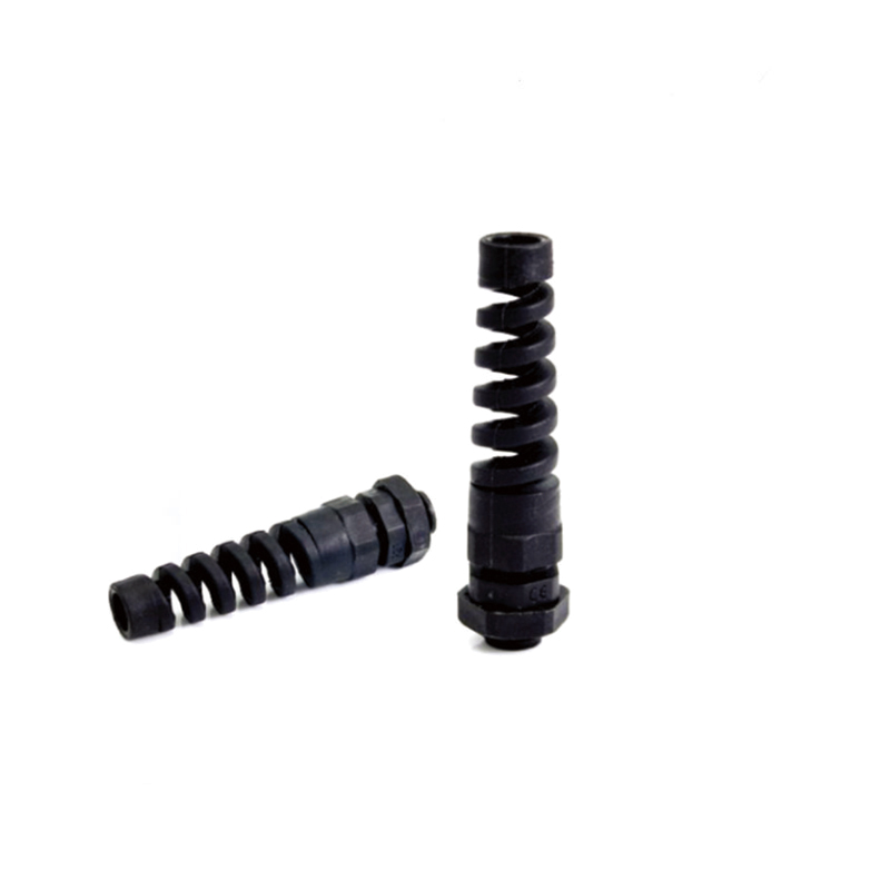
The PG25 cable gland is a 15 to 22 mm part on a 32 mm thread, and on those numbers alone it cannot be told apart from the metric gland beside it. Every dimensional column matches. What separates the two is not in the table at all, and that is the point of this page: at this size the choice is made by what the cable is carrying, not by what the calliper says.
PG25 also sits where shielded motor cable becomes routine, so the standard and EMC versions have to be considered together.
The Numbers That Define a PG25 Gland
المعلمة
PG25 standard gland
What it decides at the panel
الخيط
PG25, 80 degree thread form
Matches PG locknuts and PG adapters only
Cable range
15 to 22 mm sheath O.D.
The sheath, not the shield, which has its own diameter
Thread outside diameter
32 mm
The figure the hole is derived from
Mounting hole
32 to 32.2 mm
Two tenths of clearance, no more
Thread length GL
10 mm
Must cover panel, washer and locknut together
طول الرابطة
29 mm
Body length behind the panel
Spanner size
35 mm across flats
One hex, and a larger one than the sizes below
Fifteen to twenty-two millimetres is a wide band, and the width is deliberate. Seven millimetres of clamp travel covers four-core cable from about 2.5 mm² to 16 mm², which is why this size is stocked rather than selected case by case. Where the band gets difficult is at its ends, and the lower end is the harder one.
Fifteen Millimetres Is a Hard Edge
PG25 starts at 15 mm and the sizes below it stop at 14 mm. PG19 and M25 both clamp 10 to 14 mm, and PG21 clamps 13 to 18. So a 14.5 mm cable falls between the two, and a 15 mm cable sits exactly on the lower limit of this gland.
The limit is written as a range, but it is not a comfortable operating point. A seal that closes at its minimum has the least rubber under compression and the least tolerance for an out-of-round sheath or a damaged jacket. A cable measuring 14.7 mm at one point along its length will not seal reliably in a 15 mm gland.
Treat the first half millimetre of any range as a warning rather than an allowance. For a cable at 15 to 15.5 mm the useful question is whether PG21 at 13 to 18 mm gives a better position in its band, not whether PG25 will accept it. It will accept it. That is not the same as sealing it.
Three Parts in the 15 to 22 mm Band
The catalogue offers three glands for this cable band, and they are closer together than at any other size in the series.
Part
Cable range
مؤشر الترابط O.D.
Mounting hole
GL
طول الرابطة
Spanner
M32 × 1.5
15 to 22 mm
32 mm
32 to 32.2 mm
10 mm
29 mm
35 mm
PG25
15 to 22 mm
32 mm
32 to 32.2 mm
10 mm
29 mm
35 mm
M33 × 1.5
15 to 22 mm
33 mm
33 to 33.2 mm
10 mm
29 mm
35 mm
Six columns and one difference: the thread form, plus a single millimetre of diameter in the case of M33. Two of the three share a hole outright, so a through hole at 32 to 32.2 mm takes either PG25 or M32 without modification. There is no cable in the band that one takes and the others refuse.
Stated plainly: at 15 to 22 mm, thread and cable diameter are not the deciding variables. The hole in the panel and the thread used elsewhere in the plant have already decided them, and once those are fixed the dimension table has nothing further to say.
What the Table Does Not Describe
If the dimensions cannot choose between these parts, the decision has to come from somewhere else, and at this cable band that somewhere is usually the shield. PG25 is the size at which shielded motor and drive cable becomes routine: a four-core screened cable for a 7.5 to 15 kW motor lands squarely in the 15 to 22 mm range.
A standard gland seals the sheath and grips it, and does nothing with the braid or foil. An EMC gland adds a third function: a low-impedance path from the shield to the enclosure wall, so interference picked up along the cable is drained to earth instead of radiated inside the cabinet. No figure in the dimension table describes that function, which is why two glands with identical dimensions are not interchangeable products.
What the EMC Version Changes
Three features do the work, and each has a failure mode worth knowing.
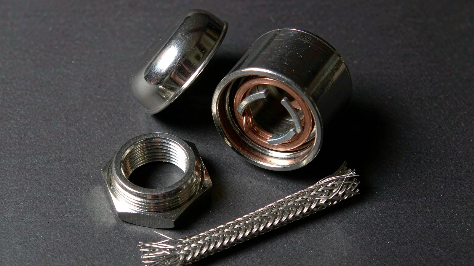
The contact spring. A copper alloy spring ring sits inside the body with fingers that splay outward as the cap is tightened. Pressure comes from the spring rather than the installer’s wrist, so the contact survives vibration. The conducting chain runs spring, body, enclosure wall, and the thread is a joint in that chain, so a powder-coated enclosure needs the coating removed at the entry face or an earth tag under the body.
The open fingers. With the cap loose the fingers stay open, so the cable can be rotated and positioned without dragging the braid across the contact edges. Cheap copies close early and scrape the shield during adjustment, a defect you cannot see after assembly.
The independent fits. The cap sets the sheath seal and the spring sets the shield contact. Two separate closures on two separate diameters, which leads straight to the most common ordering error at this size.
The contact spring sits in the body bore, with fingers that stay open until the cap closes them onto the braid.
Specify the Shield Diameter, Not Just the Cable
A PG25 gland makes two fits, and the published range describes only the first. The seal closes on the outer sheath; the spring closes on the shield underneath it. A cable with a thick jacket and a small braid can sit comfortably inside 15 to 22 mm and still present a shield diameter the spring cannot reach.
For any shielded cable, quote two measured figures: the overall sheath diameter and the shield diameter with the jacket stripped back. The first selects the size, the second confirms the gland. Suppliers who quote only the cable OD are quoting half a specification, and the missing half is the one that decides whether the shield is bonded or merely touching.
الميزة
Standard PG25
EMC PG25
Thread and mounting hole
PG25, 32 to 32.2 mm
PG25, 32 to 32.2 mm
Cable range (sheath)
15 to 22 mm
15 to 22 mm
Thread length GL
10 mm
10 mm
Spanner size
35 mm
35 mm
Body length
29 mm bonding length
Longer, to house the contact chamber
Shield termination
None; the braid is left to the installer
360 degree spring contact, no pigtail
Earth path
Through the body and thread only
Spring, body and enclosure wall, with earth tag option
Body material
Nickel plated brass or stainless
Nickel plated brass or stainless 304/316L
Note the body length row. The contact chamber sits behind the thread and adds length the standard part does not have, so an EMC gland in the same size is not a drop-in replacement in a shallow box. Ask for the EMC datasheet rather than assuming the standard figure applies.
Thread Length 10 mm and the Panel Stack
Ten millimetres is one more than PG21 and one less than PG29, and on a 3 mm plate with a 3 mm washer and locknut stack it leaves four millimetres of engagement. That is comfortable. On a 6 mm plate it leaves one millimetre, which is not.
Two things push this size towards a longer thread more often than the smaller sizes. The cables are heavier, so the gland is more likely to sit on a structural panel than a thin cover. And EMC glands are frequently fitted with an earth tag under the body, which is a millimetre of stack that never appears on the enclosure drawing.
The 29 mm body behind the panel is shared with M32 and M33 and is two millimetres longer than PG21. In a crowded drive cabinet that is the space the gland’s tail competes for with terminal blocks and cable duct.
Spanner 35 and the Entry Pitch
PG25 is where the spanner jumps. PG21 carries 30 and 32 mm hexes, PG25 carries a single 35 mm hex, and the next size up goes to 40. That step is larger than the thread step, and it changes how many glands fit on a plate.
Entry pitch is set by the wrench that has to swing on the largest hex, not by the thread diameter. A row of PG25 glands needs more space between centres than the 32 mm thread suggests, and on a plate designed around thread diameters the last entry in the row is the one that cannot be tightened.
The single hex also simplifies the toolkit: one wrench instead of two, and no counter-hold on a separate body hex.
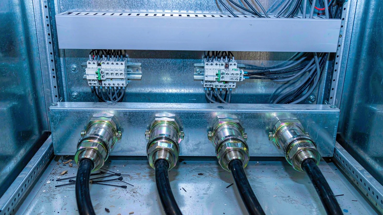
Entry spacing on a drive gland plate is set by the wrench that has to swing on the hex, not by the thread.
Buying PG25 With or Without Shielding
The purchase order for this size needs one field that the standard catalogue does not prompt for, and that is the shielding requirement.
Field to specify
Example for this size
What it prevents
Thread system and size
PG25, not “32 mm”
An M32 supplied against a PG entry
Shielded or not
EMC, 360 degree contact
A standard gland on a VFD cable
Sheath diameter
18 to 20 mm measured
A part sitting at the edge of its range
Shield diameter
Measured with the jacket stripped
A spring that closes on nothing
Hole already present
32 to 32.2 mm through hole
Discovering a tapped entry after delivery
Body length
Standard 29 mm, or EMC chamber length
An EMC gland that will not fit a shallow box
Accessories
Locknut, earth tag, shroud in PG25
Metric hardware on a PG thread
Our PG25 cable gland page carries the stainless version for outdoor and washdown service, and the EMC cable gland range covers the shielded version from M12 to M63 and PG7 to PG48, with the same mounting holes as the standard series so an existing entry can take either. Background on how the spring terminates a braid is in our guide to EMC cable glands and the 360 degree shield termination article.
Minimum order quantity for brass is normally 1,000 pieces per size with no tooling charge, and trial orders of 100 to 500 pieces are usually accepted at a slightly higher unit price. Stainless steel starts at 300 pieces per size.
الأسئلة المتداولة
What size hole does a PG25 cable gland need?
32 to 32.2 mm. That is the thread outside diameter plus about two tenths of a millimetre of clearance.
What cable does a PG25 gland take?
15 to 22 mm sheath outside diameter. Treat the lower half millimetre as a warning rather than an allowance, because a seal at its minimum has the least tolerance for an out-of-round sheath.
Is PG25 the same as M32?
Dimensionally yes: cable range, thread outside diameter, hole size, thread length, bonding length and spanner all match. The thread forms do not, so locknuts and adapters are not interchangeable, and an M32 will not enter a tapped PG25 entry.
When should I use the EMC version instead?
Whenever the cable carries a shield that has to be bonded, which at this size usually means a motor or drive cable. The standard gland leaves the braid to the installer, and a pigtail connection loses shielding effectiveness at exactly the frequencies that matter.
Why does the EMC gland need a different body length?
The 360 degree contact spring sits in a chamber behind the thread, which adds length the standard part does not have. The mounting hole is unchanged, but the space needed behind the panel is not. Ask for the EMC datasheet for the exact figure.
PG13.5 is not 13.5 mm across. The number refers to nominal bore, so the thread measures 20.4 mm and needs a 20.4 to 20.6 mm hole. This guide covers the dimensions, the M20 confusion and how to identify an unknown thread.
M22 gives you M25’s cable range on M20’s thread length. Why the size exists, the five dimensions behind it, and the 0.5 mm difference that makes PG16 a trap.
Eight-step field procedure for EMC cable gland installation: screen exposure, braid fold-over, torque, enclosure bonding and the continuity check that proves the shield is bonded.
نحن نستخدم ملفات تعريف الارتباط لتحسين تجربة التصفح الخاصة بك، وعرض إعلانات أو محتوى مخصص، وتحليل حركة المرور لدينا. بالنقر على "قبول الكل"، فإنك توافق على استخدامنا لملفات تعريف الارتباط.