Strain relief is not there to protect the cable. It is there to keep mechanical load off the terminals. A cable hanging from a gland on a wall, pulled during maintenance, or vibrating on a pump transfers that force down the conductors until something gives — usually the terminal screw, the ferrule, or the conductor strands right where they leave the insulation.
A gland provides strain relief when its clamping element grips the cable jacket hard enough that the load stops there. Whether it does that is a property of the insert, the cable jacket and how the two were matched, not a property of the gland having been installed. Two identical glands on two cables can differ completely in retention.
The Three Mechanisms Inside a Gland
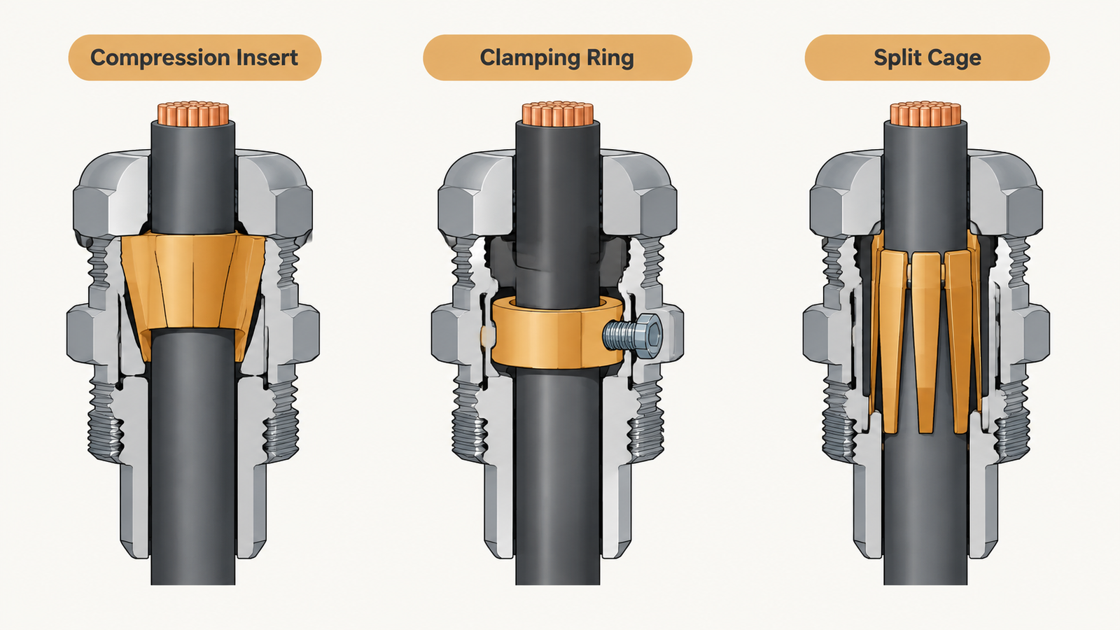
Almost every gland that provides strain relief does it with one of three arrangements, and they behave differently under load.
Mechanism
How it grips
Strength
Weak point
Tapered compression insert
Dome nut drives a soft insert down a cone; the insert closes radially on the jacket
Good for round jackets across a wide range
Grip depends on the cable being near the middle of the range
Separate clamping ring or saddle
A metal or hard-plastic ring closes on the jacket independently of the seal
Higher retention, and adjustable without disturbing the seal
Needs the exact cable diameter; rings are size-specific
Split insert with a clamping cage
Multiple fingers close on the jacket, spreading the load over a longer length
Best for flexible cable and vibration
More parts to lose and to reassemble in the right order
The first arrangement is what most people mean by “a cable gland”. It is adequate for static installations with a properly supported cable. It is not adequate for a cable that hangs, moves, or carries a connector at the far end.
There is a fourth arrangement worth knowing about, because it is the one buyers most often specify by accident: a gland with an internal clamping cage that has to be assembled in a fixed order around the jacket. It gives the best grip of the four on flexible cable, and it is also the one most often installed with a part missing, because the cage comes in pieces and the pieces look optional. If your specification calls for a clamping cage, ask for an assembly drawing with it.
Strain Relief Is Not Cable Support
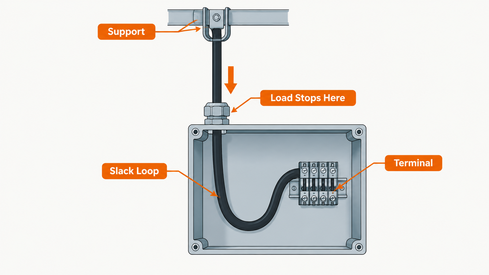
These two get conflated and the mistake is expensive. Strain relief stops tension reaching the terminals. Cable support carries the weight of the cable so that tension never reaches the gland in the first place. A gland that provides excellent strain relief will still fail if it is the only thing holding 20 metres of vertical cable.
The practical rule: the cable should be supported so that the gland sees no sustained static load. Then the gland only has to resist occasional pull, vibration and thermal movement — which is what it was designed for. If the gland is carrying weight all day, the insert creeps, the jacket necks down at the grip point, and retention falls off over months rather than failing outright.
The gland should stop the load. A slack loop after the gland keeps the conductors from carrying tension into the terminal.
Pull-Out Resistance: What Determines It
Retention is a system property of the gland, the cable and the installation. Five factors dominate, and buyers usually control only the first two.
العامل
Effect
What to do about it
Cable position in the clamping range
Middle of the range gives the best grip; the extremes give the least
Choose the size from the measured jacket diameter, not the conductor size
Jacket material and hardness
Soft PVC and rubber grip well but creep; hard jackets resist creep but are slippery
Ask for the retention figure with the jacket type in mind
Insert hardness
Harder inserts resist creep but conform less to an uneven jacket
Match the insert to the application, not to the price
Grip length
Longer contact spreads the load and resists necking
Prefer a longer body on large or heavy cables
Tightening
Too little leaves the insert unloaded; too much crushes the jacket and reduces the section carrying load
Judge by seal travel, not by force
The single most common selection error is buying by conductor cross-section. A 4 mm² cable can have a jacket anywhere in a wide band depending on insulation type and manufacturer, and the clamping range is defined on the jacket. The thread size chart shows the ranges; measure the cable before choosing a row from it.
Where Glands Fail to Hold
Four failure patterns account for nearly all of the retention complaints we see, and none of them are manufacturing defects.
Cable at the top of the range. The insert closes on the largest diameter it was designed for and has almost no travel left. It seals, it does not grip. Moving one size up fixes it; over-tightening does not.
Bend radius ignored. A cable forced into a tight bend right at the gland puts a side load on the insert, and the grip becomes a pivot. The jacket deforms on one side and retention drops.
Jacket creep under sustained load. Vertical drops and unsupported horizontal runs. The jacket slowly necks down where the insert grips, the insert loses its interference, and after a year the gland that passed a pull test at commissioning no longer holds.
Over-tightening. Beyond the correct compression the insert cuts into the jacket. A notch is a stress concentration, and the cable eventually fails at the notch rather than pulling out — which looks like a cable fault, not a gland fault.
Nylon and Brass Behave Differently Under Load
The material changes how the clamp behaves over time, not just how strong it is on day one.
الممتلكات
Nylon (PA66)
Brass and stainless steel
Initial retention
Good, with a compliant insert
Good to high, especially with a clamping ring
Behaviour over time
The body and insert creep under sustained load; grip relaxes
No creep; the clamp holds the same load for years
Under vibration
Better damping, but the nut can walk if not locked
Transmits vibration to the panel; needs a locking feature
That creep behaviour is why a nylon gland on a vertical cable needs support at a shorter interval than a brass one. It is not a defect — it is what the material does — and it is the reason the nylon range and the brass range are specified for different duties rather than ranked.
Testing Retention
Cable gland standards include a cable retention test: a defined tensile force is applied to the cable and the movement at the gland is measured. The required force scales with the cable diameter, and the figures live in the standard rather than in a product catalogue — which is why a catalogue that quotes a single “pull-out force” for a size should be read carefully.
In the field, the check that matters is whether the cable moves when pulled by hand after installation. It is crude, but it catches the two failures that actually happen: the insert that never closed, and the cable that was never in the range it was sold for. Do it before the enclosure is closed, on every gland, and do it again at the first maintenance visit on anything vertical or vibrating.
Record the result, even informally. A retention check that is not written down is a check that will not be repeated, and the second inspection is the one that matters because creep and vibration take months to show. A line per gland in the commissioning file — size, cable diameter, pass or fail — costs a few minutes and settles most arguments about whether the gland or the cable caused a failure two years later.
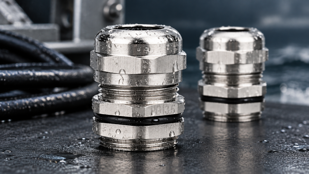
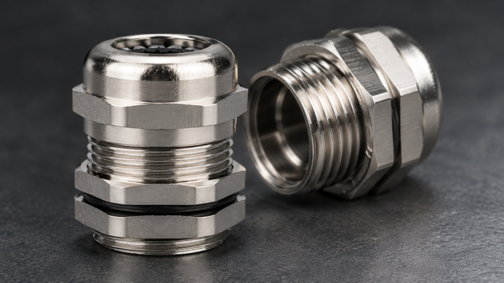
Three ways to grip a jacket: a tapered insert, a separate clamping ring, and a split cage. Only the second and third grip independently of the seal.
When You Need a Separate Clamp
A gland is the wrong tool for four situations, and recognising them early avoids a callback.
Situation
Why the gland is not enough
What to add
Long vertical drop
Static weight is continuous; the insert creeps
Cable cleat or support bracket above the gland
Moving or vibrating equipment
Cyclic load works the jacket at the grip point
Clamp close to the gland plus a service loop
Connector on the far end
Anyone can pull the connector and the load goes straight to the terminals
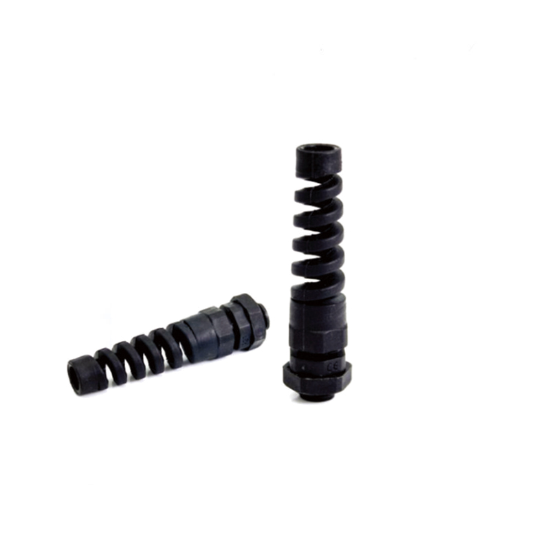
Internal cable tie-down or a strain relief boot
Very large or stiff cable
The gland cannot develop enough grip without crushing the jacket
Dedicated cable entry plate with a clamp bar
Specifying Strain Relief in an Order
Retention is rarely written down, which is why it is rarely delivered. Four lines in the specification close the gap.
State the jacket diameter for the actual cable, not the nominal size, and say whether it is at the edge of the range.
Name the duty — static, hanging, vibrating, or frequently disconnected — so the supplier can recommend the mechanism rather than the cheapest body.
Ask for the retention test standard the product is qualified to, and for the report if the application is safety-related.
Say whether a clamping ring is required, because on many ranges it is an option and not the default.
Where the cable is armoured, the mechanical duty changes completely: the armour has to be clamped and earthed, and the jacket grip becomes secondary. That is a separate design covered in the armoured cable gland guide, and the double compression arrangement that separates seal from clamp is compared in single vs double compression.
الأسئلة الشائعة
Does a cable gland provide strain relief?
Only if its clamping element grips the jacket with enough force to stop the load reaching the terminals. A tapered insert at the middle of its range does this well; the same gland at the top of its range seals without gripping.
How much pull should a gland withstand?
The requirement scales with cable diameter and is defined in the cable gland standard. The useful field check is simpler: after installation, pull the cable by hand and confirm it does not move.
Is a metal gland better for strain relief than nylon?
For sustained loads yes, because it does not creep. For light static cable in a dry panel, a nylon gland with a good insert is entirely adequate and cheaper.
Why does my cable slip after a few months?
Almost always jacket creep under sustained load, which means the gland is carrying weight it should not be carrying. Add support above the gland and re-check the size selection.
Can I add strain relief after installation?
Yes, in most cases. A clamping ring can be fitted on ranges that offer it, or a cleat can be added above the gland without disturbing the seal.
Send us the cable list with jacket diameters and the duty for each entry and we will tell you which sizes need a clamping ring rather than a standard insert. The installation guide covers the fitting sequence, and the torque guide explains how much compression the insert should see.
Why 316 stainless steel cable glands fail at sea, and what the position of the entry has to do with it. Exposure zones, crevice corrosion, free iron, washdown and installation discipline.
304 and 316 stainless steel cable glands differ in one element. What molybdenum does at a pit, why the magnet test proves nothing, and which parts the certificate actually covers.
PG and metric cable glands are separate thread systems, not two names for one fitting. Flank angles, the nearest-size table, why PG13.5 will not enter an M20 hole, and when an adapter is the right answer.
نحن نستخدم ملفات تعريف الارتباط لتحسين تجربة التصفح الخاصة بك، وعرض إعلانات أو محتوى مخصص، وتحليل حركة المرور لدينا. بالنقر على "قبول الكل"، فإنك توافق على استخدامنا لملفات تعريف الارتباط.