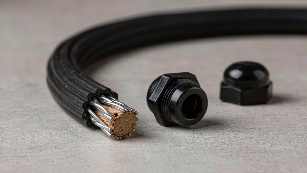
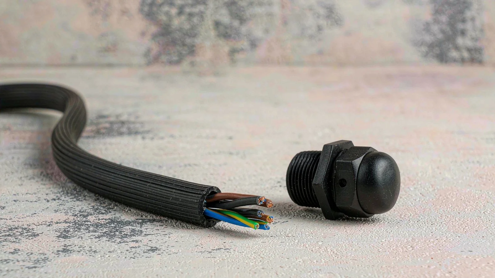
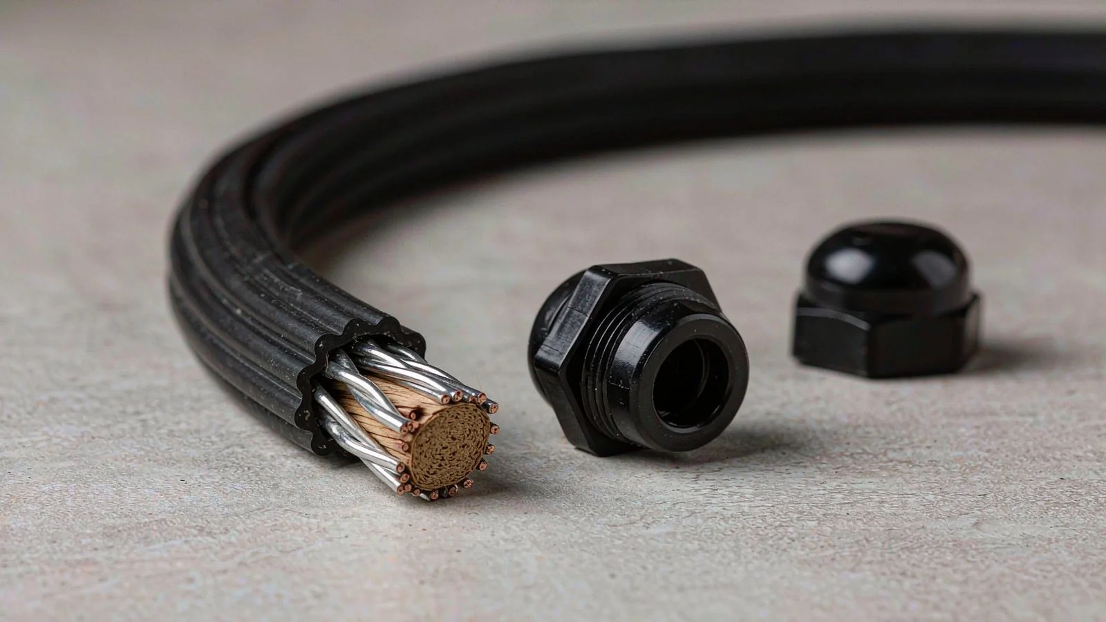
Two different lengths get called stripping length, and mixing them up is the root of most sealing failures at the enclosure entry.
The first is the jacket strip — how much outer sheath you remove so the conductors can reach the terminals. The second is the insert reach — how far the intact jacket has to extend into the gland so the sealing insert closes on sheath rather than on air, filler or bare copper. The number most installers quote is the first. The number that decides whether the gland holds its IP rating is the second.
The Short Answer: Strip to the Insert Seat, Not to a Number
There is no universal stripping length for cable glands, for the same reason there is no universal tightening torque: the insert seat sits at a different depth in every body, and the seal only works where the sheath is still cylindrical and intact. What you can standardise is the rule — the jacket must reach past the sealing insert and stop before the conductors need to bend — and then measure that depth on the gland you are actually fitting.
A gland whose insert closes on the filler tape, on a bunched screen or on exposed cores is not sealed, no matter what the label says. A gland whose jacket is stripped too far back leaves the insert gripping a tapered, splayed sheath edge that cannot compress evenly.
The jacket cut edge is the only part of this assembly that seals. Everything to the left of it is inside the gland; everything to the right is inside the enclosure.
Four Things That Decide the Strip Length
The figure you write into a work instruction is produced by four inputs, and only one of them is under the fitter’s control.
Input
Effect on the strip length
Who decides it
Insert seat depth
Sets the minimum jacket length that has to survive inside the gland
The gland body design — read it off the gland, not from another product
Panel thickness
Adds to the length the jacket must span before it can be cut
The enclosure, not the gland
Cable construction
Decides which layer the gland is allowed to grip: jacket, inner sheath or bedding
The cable datasheet
Terminal position
Sets how much conductor has to reach into the enclosure once the jacket ends
The cabinet layout
Four inputs, one output. Only the terminal position is negotiable at the panel.
Where the Seal Actually Sits
On a standard gland the sealing insert is compressed by the dome nut and grips the sheath a few millimetres inside the body. On a split gland the insert is split lengthwise, so it grips the sheath along its whole length rather than at one ring — which means the jacket has to run through the entire insert, not just into it. On an armoured gland the seal sits on the inner sheath or the bedding, because the outer jacket is cut back to expose the armour. Three constructions, three different places where the jacket must still be intact.
Strip Length by Cable Construction
This is the table to check before you cut. The question is not how long the strip is, but which layer the gland is allowed to grip.
Cable construction
Outer jacket at the gland
What the insert must grip
Where the screen or armour goes
Unshielded flexible cable
Continuous, reaches past the insert seat
The outer jacket
Nothing to terminate
Shielded / screened cable
Continuous on a standard gland; stripped back on an EMC gland
Jacket on standard, folded screen over the contact ring on EMC
EMC: clamped to the body. Standard: cut back, never bunched under the insert
Armoured (SWA / STA)
Stripped back to expose the armour
Inner sheath or bedding
Armour clamped by the armour ring and bonded by the earth tag
Single-core with thin wall
Continuous
The jacket, at the smallest insert in the range
Nothing to terminate
Multi-core into a multi-hole insert
Continuous on every core, per bore
Each jacket in its own bore; unused bores blanked
As per the cable type of each core
The gland seals on the outermost continuous round layer at the entry point. Stripping one layer too far moves the seal onto a surface that was never meant to be gripped.
The pattern: the gland always seals on the outermost layer that is continuous and round at that point. Strip one layer too far and the seal lands on a layer that is not designed to be gripped — filler, tape, screen braid or bare conductor.
How Much Conductor to Leave Inside the Enclosure
Once the jacket ends at the insert seat, the remaining length is set by the terminal, not by the gland. Enough to reach the terminal block with a service loop that allows the conductors to be re-terminated once, and not so much that the loop presses against the enclosure door or the DIN rail.
The directional rule matters more than the number: measure from the insert seat to the terminal, add the loop, and cut the conductors to that length after the gland is tightened — not before. Cutting first and fitting second is how cables end up 30 mm short inside a cabinet that has already been drilled.
Measuring the Insert Seat on the Bench
You do not need a drawing to get this right, and you should not trust a number copied from a different gland. Take the gland apart, seat the insert into the body as it will sit when assembled, and measure from the face of the insert to the end of the body thread. That dimension plus the panel thickness is the minimum jacket length that has to survive inside the gland. Add the length you need inside the enclosure and you have the strip length for that cable, on that gland.
Do it once per gland size and write the result into the work instruction. It takes two minutes and it removes the single most common reason a gland leaks on first commissioning.
Strip Length for Split and Multi-Hole Glands
Split glands are the case where the rule is easiest to get wrong, because the insert can be opened around the cable after the jacket has already been cut. Two consequences:
The jacket must run the full length of the slit insert. A split insert that closes partly on sheath and partly on cores will leak along the boundary between them.
The cut edge of the jacket must be square and clean. A ragged or diagonal cut on a split gland leaves a gap that the insert cannot close, because the two halves compress the insert along its axis rather than squeezing it radially.
On multi-hole inserts the rule applies per bore: each cable needs its own intact jacket through its own hole, and every unused bore needs a blank. One cable with a short jacket spoils the seal for the whole insert, not just for its own bore. The split cable gland sizing and installation guide covers the assembly order; this page covers where to cut.
Three Failures the Wrong Strip Length Causes
None of these show up as a strip-length problem when they happen. All three do.
Symptom
What it means
Fix
Water tracks along the cable into the enclosure
Insert closed on filler, tape or a bunched screen instead of on the jacket
Re-strip shorter so the jacket reaches the insert seat; do not tape over the gap
Insert splits or extrudes on tightening
Jacket stripped too far back, so the insert is squeezed onto a tapered sheath edge or onto cores
Replace the insert and re-terminate with more jacket left on
Cable pulls out under load despite full torque
Insert gripping conductors rather than sheath, so there is nothing for it to hold
Re-strip to the seat; check the cable is inside the gland’s stated range
All three are strip-length failures, and all three are usually blamed on the gland.
Writing Strip Length into a Work Instruction
A useful work instruction states the rule and the measurement, not just a number: “jacket to reach the insert seat, seat depth measured per gland size on the sample board, conductors cut after tightening”. A bare number in a table gets applied to a different gland the moment the BOM changes, and nobody notices until the enclosure fails a hose test.
If you are assembling to a customer specification, put the insert seat dimension and the cable construction on the drawing as well as the strip length. The two together are what a fitter can actually check with the parts in hand.
Jacket back to the insert seat, cores intact, screen or filler handled per the gland type. The cut edge is square for a reason.
الأسئلة الشائعة
How much jacket should I strip for a cable gland?
Far enough that the jacket reaches past the sealing insert seat, and no further than the point where the conductors need to bend inside the enclosure. The depth is specific to the gland body — measure it on the gland you are fitting rather than using a number from another product.
Should the screen or braid be left under the gland?
Only on a gland designed to terminate it. On an EMC gland the screen is folded back over a cone or contact spring and clamped; on a standard gland the screen is cut back and the seal lands on the jacket. Leaving a screen bunched under a standard insert creates a leak path along the braid.
Can I strip the cable after it is inside the gland?
On a split gland, sometimes — but only if the strip line is measured first and marked. On a standard gland the cable has to be stripped before it is inserted, because the jacket has to pass through the insert as one continuous piece.
Does the strip length change for armoured cable?
Yes. The outer jacket is stripped back far enough to expose the armour, the armour is clamped by the gland’s armour ring and bonded by the earth tag, and the seal then lands on the inner sheath or bedding. The strip length is set by the armour clamp position, not by the insert seat alone.
What if the insert does not reach the jacket?
Then the gland is the wrong size, or the cable range on the datasheet does not match the cable. Do not solve it by stripping less and forcing the insert — the insert will extrude, split, or grip the cores instead of the sheath. Go one size down, or change the insert.
Key Takeaway
Strip to the insert seat, measure that seat on the gland in your hand, and cut the conductors after the gland is tight. The jacket edge is the only part of the cable that seals, so treat its position as the specification and the total strip length as a consequence.
If you are specifying glands and cable together, send the cable construction and the enclosure interface and we will confirm the insert and the seat depth for that combination — the main types guide covers which construction suits which cable, and the cable gland installation guide runs through the assembly sequence.
A practical guide to installing explosion proof cable glands: barrier compound curing, entry thread engagement, tightening criteria and the inspection record that IEC 60079-14 expects.
If you ever typed “are cable glands waterproof” into Google, you not alone. It one of those procurement-and-engineering questions that sounds simple, but it hides a bigger issue: “waterproof” is not a precise engineering specification. In real projects—outdoor telecom cabinets, marine sensors, washdown food lines, rooftop PV combiner boxes—what you really need is a cable […]
نحن نستخدم ملفات تعريف الارتباط لتحسين تجربة التصفح الخاصة بك، وعرض إعلانات أو محتوى مخصص، وتحليل حركة المرور لدينا. بالنقر على "قبول الكل"، فإنك توافق على استخدامنا لملفات تعريف الارتباط.