A PV Entry Has to Last Twenty-Five Years Unattended
Almost every other cable entry on a site is inspected at some point. A gland in a plant room is walked past daily, and a gland on a machine is opened when the machine is serviced. A gland on a solar array is different: it is installed once, on a roof or in a field, and then nobody looks at it for a decade. The economics of the installation depend on that assumption, which is why the entry has to be selected for the whole service life rather than for the day of commissioning.
That single fact changes the selection question. On an industrial enclosure the question is whether the gland is tight enough. On a PV array it is whether the gland is still tight after twenty-five years of sun, frost, thermal cycling and cable movement — with no maintenance access and no way to observe a slow failure until water has already reached the terminals.
What Is Different at the Module End
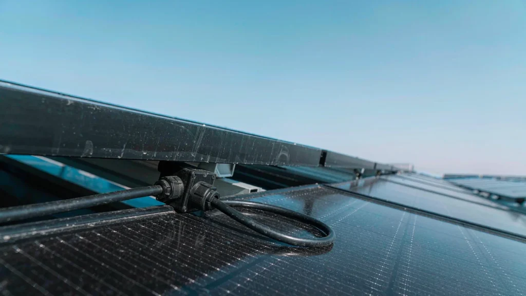
Four conditions separate a PV entry from a general outdoor entry. The first is ultraviolet dose: a roof-mounted entry sees direct sun for the whole of every clear day, and reflected light from the modules themselves adds to it. The second is thermal cycling: the entry is at its hottest in the afternoon and at its coldest before dawn, every day, and the cable and the enclosure expand at different rates.
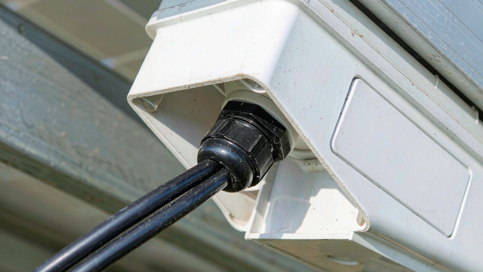
The third is that the cable is often small, stiff and double-sheathed, with a hard outer jacket that resists being compressed by a soft insert. The fourth is that the entry is frequently on a moulded plastic component — a module junction box or a small enclosure — where the wall is thin and cannot take much torque before it distorts. An industrial gland reused on a module frame inherits none of the assumptions it was designed for.
The Cable Decides the Gland Size
Solar cable is specified by its own standard — H1Z2Z2-K under EN 50618, or PV1-F under the TÜV scheme — and both are cross-linked, double-insulated and deliberately tough. The outer jacket is harder than a flexible control cable of the same diameter, which matters because a gland seals by compressing an elastomer against that jacket. A hard jacket needs a seal with enough compliance to conform to it, and a cable sitting at the very top of a gland’s clamping range leaves almost no compliance left.
Circuit at the array
Typical conductor
Typical overall diameter
Selection note
String cable, module to module
4 mm²
Roughly 5.5–6.5 mm
Small entries; do not use an oversized gland “for margin”
String cable, longer runs
6 mm²
Roughly 6.5–7.5 mm
Measure the jacket, not the conductor
Array submains and DC trunk
10 mm² and above
From about 7.5 mm up
Strain relief becomes the governing requirement
AC output from inverter
Multi-core armoured or flex
Varies widely
Treat as an industrial entry, not a PV entry
The diameters above are typical, not a specification. Jacket thickness differs between manufacturers and between fire-performance grades, and the only reliable input is the cable datasheet value or a measurement with a calliper on the actual drum. A gland selected from the conductor size alone is the most common sizing error on PV work.
The module end is a small cable, a thin wall and full sun — three conditions the industrial gland default was not chosen for.
Outdoor Exposure: UV, Ozone and the Colour Black
Two materials are used for PV entries: polyamide and nickel-plated brass. Both survive sunlight if they are selected correctly, and both fail in ways that are visible only when the gland is removed.
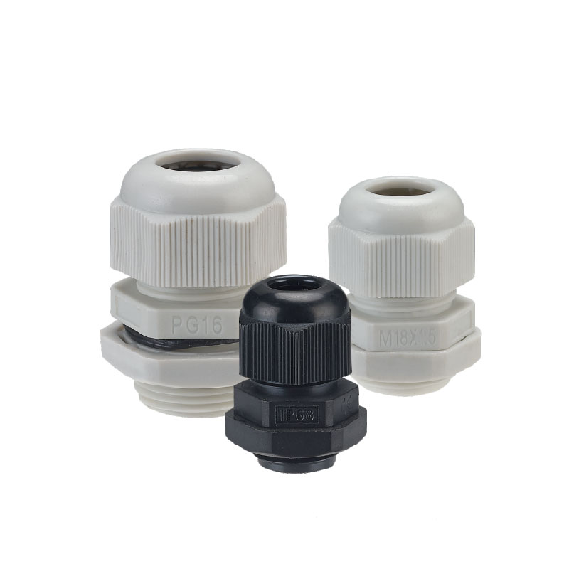
Polyamide is not naturally UV-stable. The black grades used for outdoor cable glands are stabilised with carbon black, which absorbs ultraviolet radiation before it can break the polymer chain. A grey or white nylon gland on a roof will chalk, embrittle and crack at the thread root within a few years. This is why outdoor nylon glands are black almost without exception, and why a colour change in the specification is not a cosmetic decision.
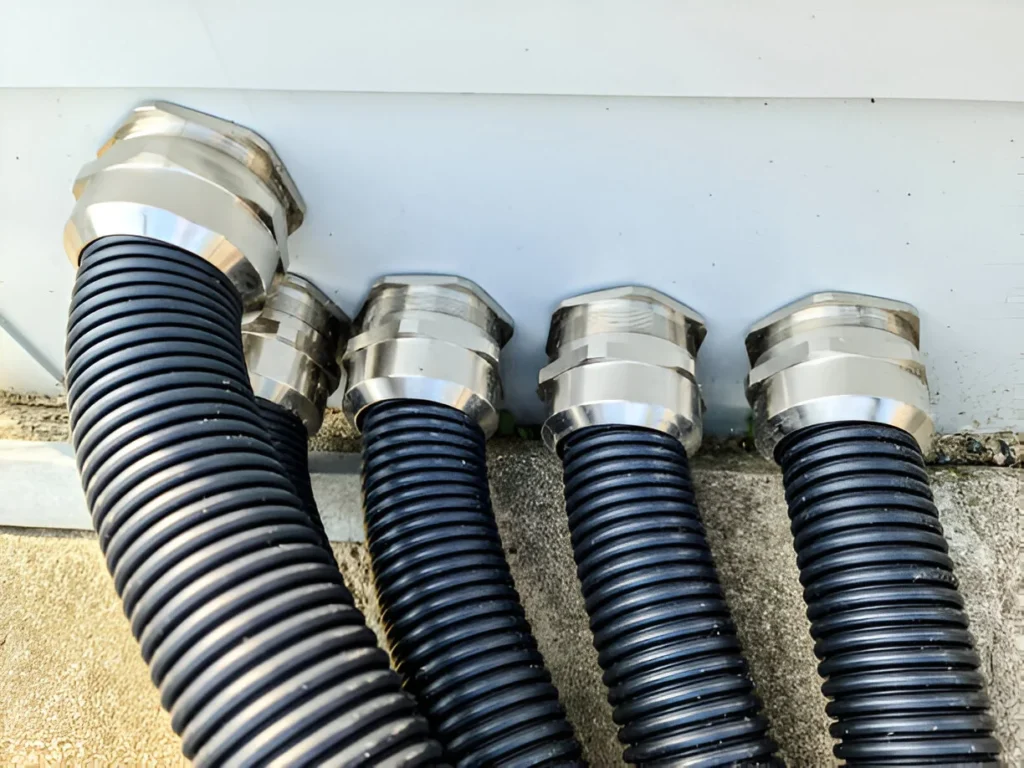
Brass is immune to UV but depends on its plating. A nickel-plated brass gland on a roof is exposed to rain, condensation and, in coastal or agricultural sites, chlorides and ammonia. Where the plating is damaged during installation — a spanner slipped on the dome nut is enough — the exposed brass corrodes and the corrosion products occupy the thread, which is a mechanical problem as well as an appearance one.
Thermal Cycling Is the Real Test
An entry that passes a hose test on a cool morning can still leak after a year of cycling. The mechanism is straightforward: the elastomer is compressed at installation, the assembly heats up, the elastomer softens and the compression relaxes slightly, then the assembly cools and the elastomer stiffens in a slightly different shape. Repeat that daily and the seal progressively loses contact pressure.
This is compression set again, aggravated on a roof by two things: the entry sits where air movement is highest, so the temperature swing is larger than at ground level, and the cable is often fixed short, so thermal expansion reaches the gland as a small axial load instead of being absorbed by a service loop.
The answer is not a harder seal. It is a seal correctly sized for the jacket, a service loop so the gland carries no axial load, and a body that does not change dimension with temperature — which is why metal is preferred where the entry is exposed and the cable heavy.
Nylon or Brass on a Roof
The choice is usually about the enclosure rather than the gland. A moulded polyamide junction box with a thin wall pairs naturally with a polyamide gland: the two expand at similar rates, the gland is light, and there is no galvanic couple. A metal enclosure, a steel mounting frame or a heavy DC cable run points to nickel-plated brass, which tolerates higher torque and holds a heavy cable without creep.
Condition at the entry
Polyamide gland
Nickel-plated brass gland
Moulded plastic junction box, thin wall
Preferred — matches expansion, low mass
Usable with a sealing washer; avoid over-torque
Steel frame or metal enclosure
Acceptable with a flat, deburred face
Preferred — no galvanic couple with the wall
Heavy submain cable needing strain relief
Limited by creep under sustained load
Preferred — no creep, higher torque capacity
Coastal or agricultural ammonia exposure
Good, if the black UV-stabilised grade is used
Good, if the plating is intact and undamaged
Direct sun on a south-facing roof
Good — black stabilised grades only
Good — no UV degradation of the body
Where the Gland Goes: Frame, Box or Enclosure
Position decides more than material. A gland on the underside of a junction box sheds water; a gland on the top face collects it. A gland on a module frame is exposed to the full thermal swing of the module itself, which runs hotter than the surrounding air. And a gland on the north face of a tilted array sees a fraction of the UV dose of one on the south face.
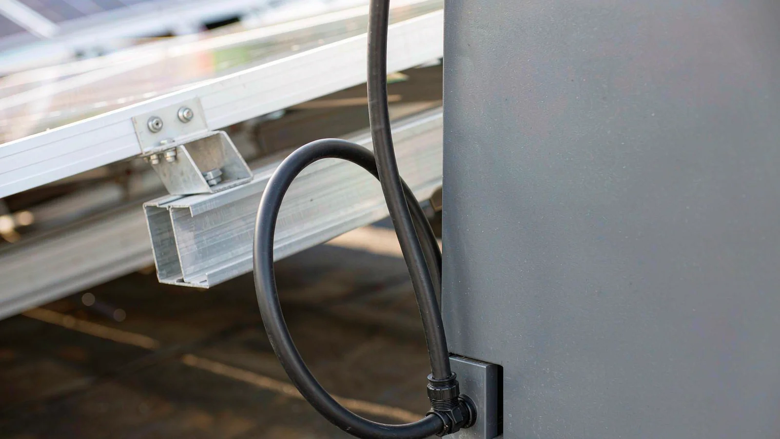
The most common preventable PV leak is a top entry without a drip loop. Where the layout forces a top entry, the cable should rise above the gland and return down, so water reaching the sheath drips off before it reaches the seal rather than tracking into it. The loop must be outside the enclosure; a loop formed inside delivers the water directly to the terminals.
The loop sits outside the box: water tracking down the sheath drips off before it reaches the seal. A loop formed inside delivers it to the terminals.
MC4 Connectors Are Not a Gland
Most module-level connections in a modern array are made with plug connectors rather than glands, and it is worth being clear about the division of labour. A connector joins two cables in free air and relies on its own sealing rings and its own mating interface. A gland terminates a cable through a wall and relies on compression against the sheath and against the enclosure face.
Glands appear wherever a cable passes through a surface: combiner boxes, inverter enclosures, monitoring junction boxes and the AC side. Connectors appear wherever two cables meet with no wall between them. Confusing the two produces the familiar defect of a connector pushed through a hole with sealant around it — an assembly that is neither a joint nor an entry, and that fails both ways.
Where a surface carries many cables rather than one, the constraint shifts from sealing to spacing: that case is covered in cable glands for PV combiner boxes.
A Specification You Can Send to a Supplier
PV enquiries go wrong when they list only the gland size. Six lines cover what actually decides the part.
Line in the enquiry
Why it decides the part
Cable type and measured jacket diameter
Sets the clamping range; conductor size alone is not enough
Mounting surface and wall thickness
Decides thread length, washer type and safe torque
Entry orientation (top, side, bottom)
Decides whether a drip loop or a shroud is needed
Highest and lowest temperature at the entry
Decides the seal compound and the body material
Coastal, agricultural or industrial atmosphere
Decides plating and whether stainless is justified
Required IP rating and test basis
Decides whether immersion testing is relevant at all
Two notes on the last line. An IP68 rating is often quoted for PV glands, but on a roof the relevant exposure is rain and spray rather than immersion, and the test that matters is the one the project actually specifies. And a gland’s IP rating applies to the gland, not to the enclosure: an IP68 gland in a hole that was drilled oversize gives an IP44 entry.
Questions From PV Installers
Can I use a standard nylon gland outdoors?
Yes, if it is the black UV-stabilised polyamide grade and the cable is within the clamping range. A grey or natural-colour nylon gland will degrade in sunlight regardless of its IP rating.
Does IP68 matter on a roof?
It is a useful indicator of sealing quality but not the requirement. Rain and spray are the actual exposure; what matters more is UV stability, thermal cycling behaviour and a seal sized to the jacket.
Why do glands on arrays fail after two or three years?
Usually compression set on an oversized gland, a jacket at the top of the range, or a top entry with no drip loop. All three are selection or geometry faults rather than manufacturing defects.
Should the gland be metal for DC circuits?
Not automatically. A metal gland on a plastic junction box brings no electrical benefit and adds a galvanic couple at the enclosure. Metal is chosen for mechanical strength, heat and enclosure compatibility.
How do I protect the cable where it enters a module frame?
Fix the cable so the entry carries no load, leave a small service loop before the gland, and route the cable so it does not chafe on the frame edge. Abrasion of the jacket upstream of the gland defeats a perfect seal.
Send the cable datasheet, the entry orientation and the site atmosphere, and we will match a gland size to the measured jacket rather than to the conductor, and flag where a drip loop or a shroud is the difference between a ten-year entry and a permanent one. The nylon range covers the black UV-stabilised sizes used on module and string entries, and the IP rating guide sets out what each rating actually tests.
من بين العديد من ملحقات التوصيلات الكهربائية، تلعب غدة الكابلات المقاومة للماء دورًا حاسمًا. فهي لا تحمي الكابلات التي تخترق أغلفة المعدات من دخول الماء والغبار فحسب، بل تعزز أيضًا من السلامة والموثوقية العامة للنظام. يساعد فهم المواد والتطبيقات الخاصة بغدد الكابلات المقاومة للماء المهندسين والمشترين في صناعات مثل الصناعة والاتصالات و [...].
تعرّف على كيفية تركيب غدد الكابلات المقاومة للماء من خلال أدلة تفصيلية خطوة بخطوة لإحكام غلق IP68 باستخدام غدد النايلون النحاسية أو الفولاذ المقاوم للصدأ من GHX.
When I speak with buyers, I notice the same pattern again and again: everyone asks for a “Waterproof Cable Gland” but what they actually need is a reliable sealing solution that matches cable size, enclosure type, operating environment, and purchasing risk. That is exactly why choosing among waterproof cable gland suppliers is not a small […]
نحن نستخدم ملفات تعريف الارتباط لتحسين تجربة التصفح الخاصة بك، وعرض إعلانات أو محتوى مخصص، وتحليل حركة المرور لدينا. بالنقر على "قبول الكل"، فإنك توافق على استخدامنا لملفات تعريف الارتباط.