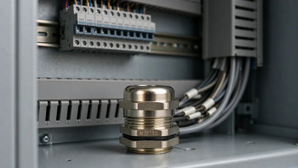
The Gland Is Decided at the Door and Paid For Inside the Cabinet
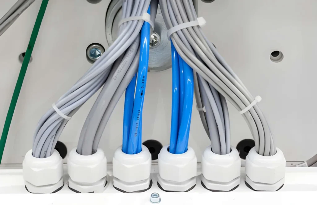
A control panel cable gland is usually selected at the last minute, by whoever is closing out the bill of materials, and picked by hole size and cable diameter because those are the two numbers on the drawing. The consequences appear somewhere else entirely: thirty centimetres inside the cabinet, at a terminal block that will not accept a wire bent tighter than the installer can force it.
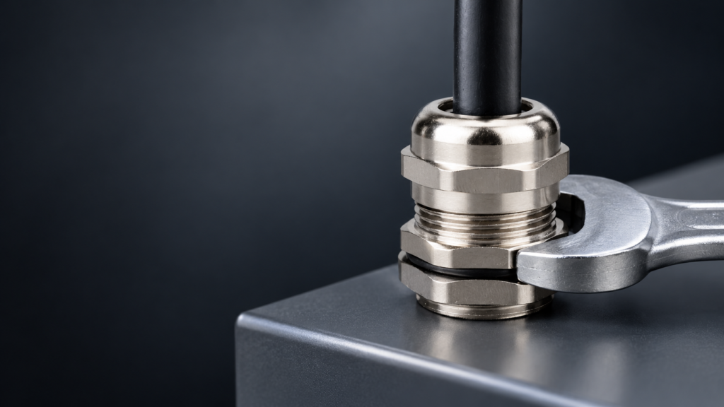
This is the inside-the-cabinet view. Wall material, thread length, locknuts and knockout quality belong to the enclosure interface. What follows is what a brass cable gland has to do once it is through the plate: reach the terminals, keep the bend radius, survive service, and leave evidence it was done correctly.
What the Gland Has to Do Inside the Cabinet
Four duties, only one of which has anything to do with water.
Hold the cable against pull so the termination is never the strain relief. In a panel the pulling force is often the installer dressing the bundle, not the machine.
Anchor the shield, if there is one, at the entry rather than at the device.
Preserve the cabinet’s protection rating at the one place a hole was cut into it.
Survive service, which in a panel means being opened, re-dressed and re-torqued several times without the seal being destroyed in the process.
Gland duty
What fails in a panel when it is neglected
Where you notice it
Strain relief
Strands break at the terminal; intermittent faults that pass a continuity test
Weeks later, during commissioning of the next panel
Shield bonding
Common-mode current finds a longer path; drive faults and encoder noise
At EMC test, or at the first nuisance trip
الختم
Water tracks along the sheath and lands on the lowest terminal row
After the first washdown or the first winter
Serviceability
Seal torn on re-entry; cable shortened each time until there is no slack
Second or third maintenance visit
Entry Height Decides the Bend Radius You Can Actually Achieve
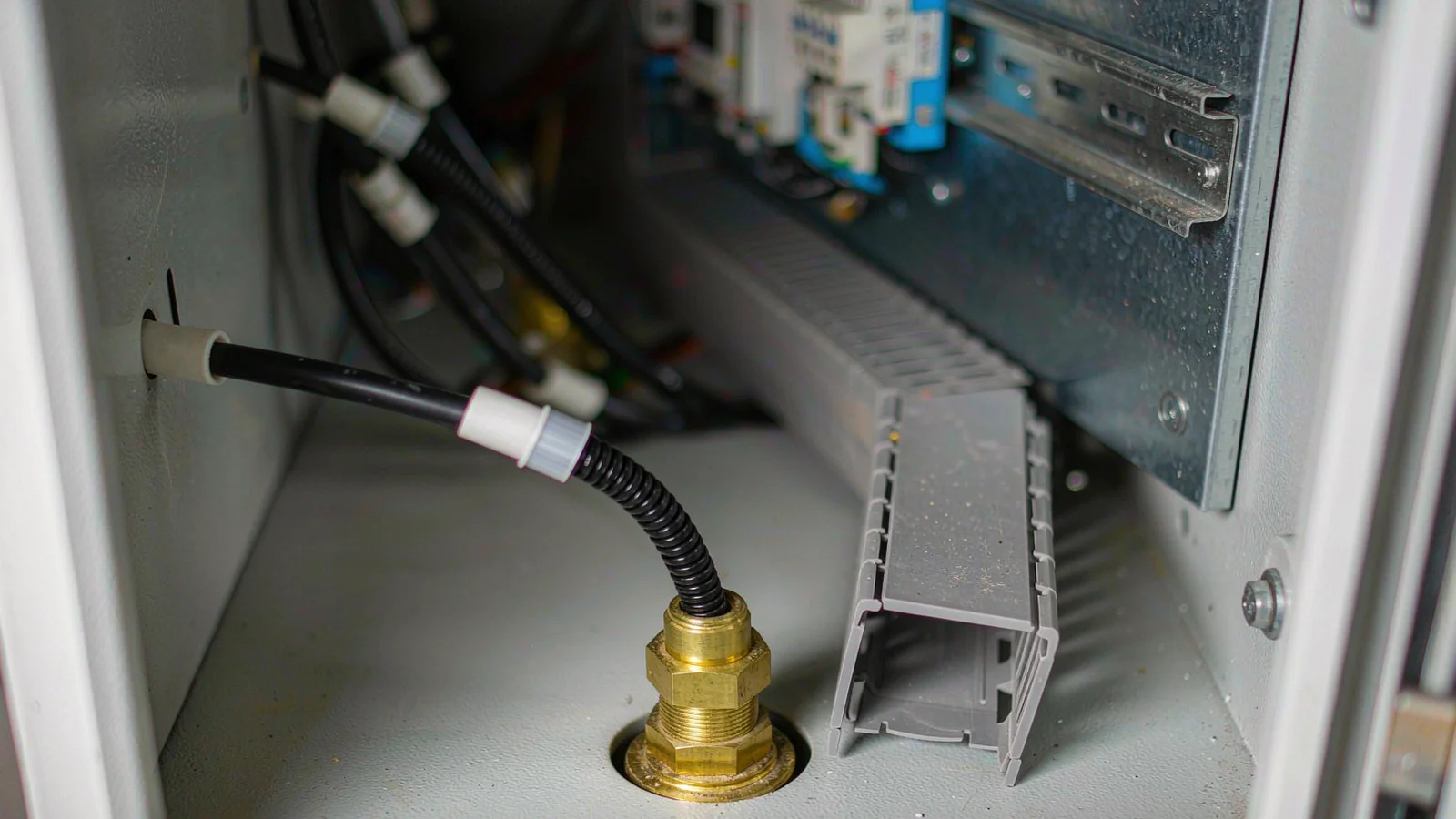
Bend radius is quoted as a multiple of cable diameter, and it is always checked against the run, never against the first hundred millimetres after the gland. That segment is the tightest point in the installation, because it is bounded by three hard objects: the back of the gland body, the wireway lip, and the backplate.
Take a 16 mm control cable with a minimum bend radius of five times its diameter. That is 80 mm of clear space needed behind the entry before the cable can turn. A gland body projecting 35 mm inside the plate, with a wireway 25 mm below the entry, leaves 40 mm. The cable gets dressed anyway, because the panel has to close — so the bend is too tight, the sheath creases, and it splits where it passes through the seal.
Two fixes, in order of preference. Group the entries so the cables that need radius share a clear band with no duct beneath them, and let small signal cables take the crowded rows. Or bring the entry in at the horizontal line of the terminal row it serves, and accept a longer route in exchange for a shorter, straighter drop.
The gland body plus the duct lip is the tightest point in the run. The cable gets dressed anyway, because the panel has to close.
Wire Duct, Terminal Rows and the Last 200 Millimetres
The run from gland to terminal is usually fine. The last 200 mm is where the cable gets abused, as it leaves the duct, crosses to the terminal and picks up whatever slack the installer left behind.
Leave the service loop in the duct, not at the terminal. Slack coiled beside a terminal block is the first thing a technician disturbs.
Fill duct to about half its cross-section. A packed duct becomes a clamp and transfers pull straight to the terminals.
Separate power and signal at the plate, and cross at 90° where they must cross. That decision is made at the gland row, because it is the only place the bundles are still distinguishable.
Gland spacing pays off here too. Lay the entries out in the order the cables reach their terminals and no bundle crosses another.
Swing Panels, Doors and Hinged Sub-plates
A gland on a hinged door is in a moving assembly and is being asked to do something it was not designed for. Its job there is to seal and grip; the door’s cable must be supported and its flexing absorbed elsewhere.
Three rules cover most of it. Run the door cable on the hinge side, so the loop tightens and loosens rather than wrapping around a corner. Clamp the cable to the door just past the gland, so movement never reaches the seal. Size the loop for the full swing plus margin, because one cut to fit exactly at 90° will pull when someone over-opens the door.
Where a door carries several cables, a multi-entry insert beats six separate glands: fewer holes, one sealing face, a replaceable part.
Shielded Cables: The Bond Belongs at the Entry
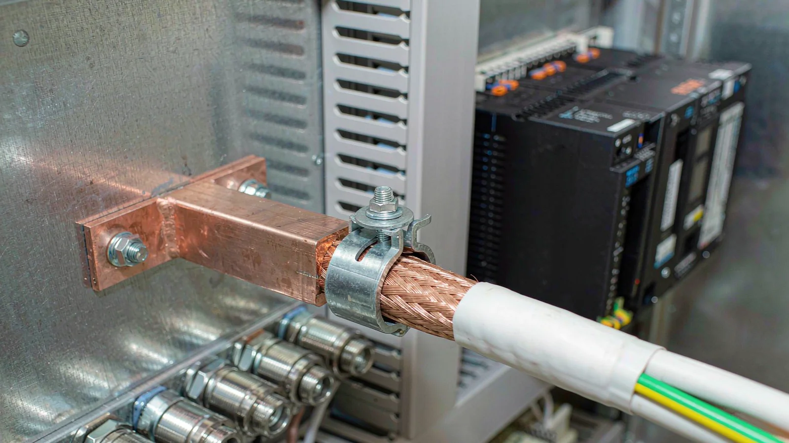
An EMC gland does not shield anything. It provides a short, wide connection between the cable screen and the cabinet metal, and the value of that connection depends on how far the current travels afterwards.
Bond the screen at the gland, then take the cabinet side of that bond to the nearest PE or EMC bar. If the bar is a metre away along the cabinet floor, the gland’s circumferential contact has been followed by a metre of thin conductor, and the high-frequency behaviour is set by the conductor, not the gland. Place shielded entries near the earth bar, or bring a section of bar to the entries — a short busbar under the gland row costs less than re-routing cables and does far more than upgrading the gland.
Do not bond at both the gland and the drive terminal and call it redundancy. Two bonds at different cabinet points create a loop carrying current nobody designed for. One bond at the entry, then a clean run to the device.
The bond is only as good as its destination. A short bar at the entry row does more than a better gland a metre from the earth bar.
Marking and Wire Numbers at the Entry
A panel that cannot be traced is a panel that gets opened twice, so the marking convention has to survive at the entry. Mark each cable just inside the gland, not at the terminal, so identification stays with the cable when the termination is moved. Use the same identifier on the gland schedule, the drawing and the ferrule. Where a gland plate carries many entries, mark it by row and column — “plate B, row 3, position 2” resolves an argument faster than any description of where the cable goes.
Record gland size and cable diameter in the as-built documentation. The next engineer will be replacing a cable, not reverse-engineering a part number from a spanner size.
Top Entry, Bottom Entry and Water in a Sealed Cabinet
Bottom entry is the default because water runs downhill and a gland facing down is not a collection point. Top entry is sometimes unavoidable, and then the cable needs a drip loop outside the cabinet before it enters, plus a sealing washer in contact with a flat face.
Entry position
What it changes
Mitigation
Bottom plate
Water runs away from the seal; cable drops into the cabinet
Keep the drop clear of terminal rows; support the bundle so it does not hang on the gland
Top plate
Gland becomes a cup; UV and rain act directly on the seal
External drip loop, downward-facing cable, verified flat sealing face
Side wall
Neutral for water, often the shortest route to a terminal row
Check clearance for the gland body and the bend inside
Door or swing panel
Adds a moving joint at a sealing interface
Hinge-side loop, clamp past the gland, margin for over-travel
Water in the bottom of a sealed cabinet is more often condensation than ingress — cabinets breathe through unfitted knockouts and past the door gasket as internal temperature swings. The gland gets blamed anyway, so fit a breather where the design allows.
What UL 508A and IEC 61439 Look At
Neither standard specifies a gland. Both constrain the space and the enclosure it is fitted to, and the gland is what eats that space.
Wire bending space is the requirement most often violated by a dense entry: a minimum space between a terminal and the nearest wall, barrier or wiring, measured in the direction the wire leaves the terminal. A gland body inside that space does not count as a wall, but the cable dressed around it does — and a bundle pressed against the back of a gland reads as a violation of intent even when the dimension passes on paper.
Enclosure type ratings are the second. A cabinet arrives rated, and cutting a hole changes the rating unless the manufacturer’s instructions cover the modification. A gland plate or a listed multi-entry insert keeps the work inside a rated component; twenty drilled holes filled with twenty glands do not.
The Panel Gland Schedule
Build the schedule by circuit function, not by cable size. Four lines cover most panels, and each carries a decision that should not be made at the bench.
Circuit type
What the entry must provide
Typical choice
Power feed, fixed
Grip, seal, earth continuity to the enclosure
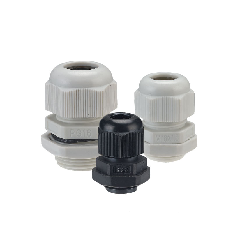
Nickel-plated brass, IP68, locknut on thin walls
Motor or drive cable, shielded
Circumferential screen bond close to the earth bar
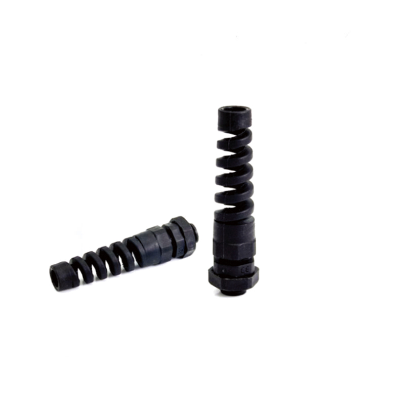
EMC gland with contact spring, brass or stainless
Signal and instrumentation
Grip without crushing, screen bond if screened
Small brass or polyamide gland matched to sheath hardness
Door or pendant cable
Seal plus external support; no load on the seal
Standard gland, clamp past the gland, hinge-side loop
Write the measured outer diameter into the schedule rather than the nominal size, and note how many spare entries you want. Two spares per entry group is a workable rule; below that, the first modification becomes field drilling on a rated enclosure. The hole size chart gives the cut-out per thread, and the enclosure entry guide covers the wall and fixing side of the same job.
Can I use polyamide glands in a control panel?
Yes, for fixed indoor cables within the material’s temperature range. The limit is mechanical: polyamide creeps under sustained pull, so use metal where the cable hangs.
Should entries go on the bottom or the side of a cabinet?
Bottom for anything that sees water or washdown. Side entry is fine indoors and often shortens the run, provided the gland body stays out of wire bending space.
Do I need an EMC gland on every shielded cable?
Only where the screen is meant to do work. A screen terminated nowhere is a drain wire with an antenna attached.
Does the gland affect the enclosure’s type rating?
The gland can carry its own rating, but the cabinet’s rating survives only if the modification is covered by the manufacturer’s instructions or made through a listed entry component.
Why is there water in a cabinet with IP68 glands?
Usually condensation, not ingress. Check whether the sheath is wet inside the gland before replacing anything.
Send the panel drawing with the cable list and terminal layout, and we will mark which entries need an EMC gland, which need a longer thread, and where entry height will fight the bend radius. The M20 standard series covers most panel control cables; the stainless range is for washdown or coastal air.
تلعب غدة الكابلات المقاومة للماء دورًا حيويًا في سوق B2B. سواء كنت مُصنِّعًا لمعدات الطاقة الشمسية أو مقاول هندسة بحرية أو مُدمج أتمتة صناعية، فإن اختيار غدة الكابلات المقاومة للماء المناسبة يؤثر بشكل مباشر على متانة وسلامة أجهزتك. هل تساءلت يومًا ما الذي يحافظ على سلامة وسلامة الكابلات لدينا، حتى في الأمطار الغزيرة [...]
نحن نستخدم ملفات تعريف الارتباط لتحسين تجربة التصفح الخاصة بك، وعرض إعلانات أو محتوى مخصص، وتحليل حركة المرور لدينا. بالنقر على "قبول الكل"، فإنك توافق على استخدامنا لملفات تعريف الارتباط.