A 360 degree shield termination is not a better earth connection. It is a change in the geometry of the return path: the cable screen is bonded to the enclosure metal around its whole circumference, in direct contact, over a short axial length, instead of being gathered into a wire and taken to a terminal.
That difference looks cosmetic on a drawing and behaves like a different product on a bench. The reason is that the screen’s current does not want to leave the cable — it wants to stay on the outside of the braid and return to its source. Every centimetre it is forced to travel as a wire is an inductance in series with that return, and inductance is what turns a screen into a radiator.
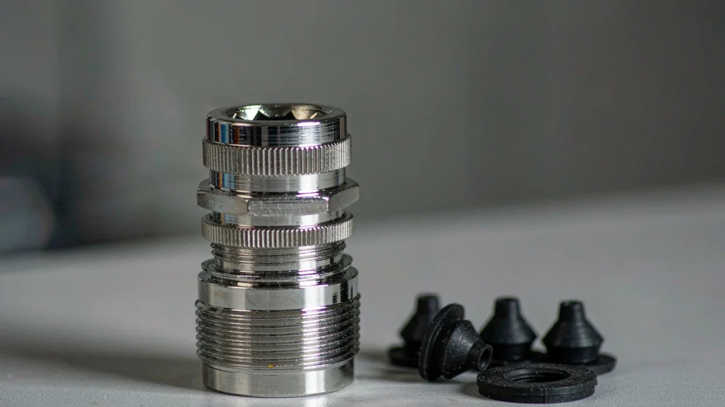
This is the mechanism that a brass cable gland with a contact spring is built to exploit, and it is also why two glands that both claim 360° contact can differ by an order of magnitude in practice.
Transfer Impedance: the Number Behind the Practice
Transfer impedance is the voltage that appears on the inside of a screen per unit of current flowing on its outside, expressed in milliohms per metre. It is the single figure that describes how well a screen does its job, and it is measured with a triaxial setup defined in IEC 62153-4-3.
The cable only contributes part of it. The termination — the transition from braid to enclosure — adds its own impedance in series, and that term frequently dominates above a few megahertz because the cable’s own contribution is deliberately small. Good screened cable sits in the low single-digit milliohms per metre; a hand-made pigtail termination can be a hundred times worse at the same point.
Two consequences follow. First, there is no useful distinction between a cable problem and a termination problem in a field failure — you have to measure or reason through both. Second, the specification that matters at purchase is not “shielded” but “what is the termination, and where does the current go next”.
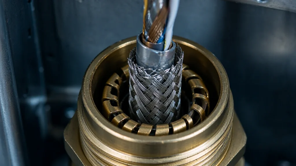
The spring is only half the bond. Bare metal under the gland, and a short path to the bar, decide the rest.
Why a Pigtail Fails Above a Few Megahertz
A pigtail is a length of braid twisted into a wire and screwed to a terminal. Its inductance is roughly what you would expect from a wire of that gauge and length: of the order of ten nanohenries per ten millimetres. That number is small enough to look harmless, which is why pigtails survive in drawings.
The impedance that matters is the reactance at the frequency of the disturbance. At a hundred megahertz, ten nanohenries is about six ohms. At a gigahertz it is about sixty. Against a screen designed to look like a fraction of an ohm, the pigtail is now the only element in the path, and the screen has stopped working.
The observable consequences are familiar: a drive that trips at a specific speed, an encoder that miscounts when a contactor closes, a sensor that reads noise only when a nearby pump runs. All of them look like device problems and are termination problems. The failure mode is also invisible from the outside, because the pigtail is inside a gland or behind a cover.
Four Ways to Get 360° Contact
The market offers four mechanisms. They differ in where the contact is made, how much current each contact carries, and what happens after a few years of thermal cycling.
Mechanism
How contact is made
Weak point
Contact spring in an EMC gland
Fingers press the braid against the gland body around the circumference
Spring loses force or sits on a painted or anodised face
Compression ring or clamp
Ring crushes the braid against a metal saddle
Torque-dependent; too much crushes the dielectric
EMC insert in a multi-cable plate
Each cable’s braid contacts a conductive insert, insert bonds to the plate
Density: many cables share one bond path
Shielded connector or backshell
Shell clamps the braid and bonds to the chassis
Shell must be metal and actually bonded, not just metal-looking
The first is what most EMC cable glands provide and it is usually sufficient, because the gland also seals and anchors. The fourth is the best electrically and the worst for service, since every disconnect breaks the bond. Choosing between them is a question of whether the joint will be opened in service, not of which is better on paper — the comparison with a standard gland sets out where the extra cost buys something.
Contact Springs: How They Work and How They Fail
A contact spring is a ring of fingers that deflect onto the braid and, at the same time, onto the inside of the gland body. Both contacts have to work. Most field failures come from the second one.
Paint under the ring. The spring sits inside a gland that is screwed into a powder-coated wall. The thread may carry the bond, or may not — either way the path is longer and less predictable than the spring suggests.
Anodised or passivated surfaces. Aluminium oxide and some passivation layers are insulators. A spring pressed onto an anodised plate is a spring pressed onto ceramic.
Contamination during assembly. Grease, sealant or cable gel on the braid raises contact resistance. It is invisible once the gland is closed.
Spring relaxation. A spring that has been compressed and thermally cycled for years loses force. Contact resistance rises gradually and nothing announces it.
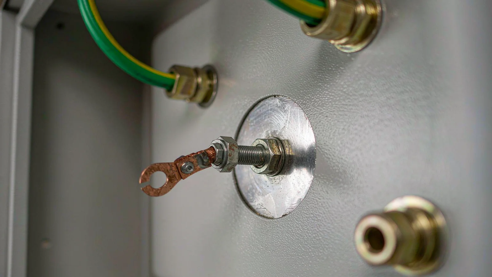
The practical answer is a bare metal landing area, masked before painting, with the spring bearing on it, and a visible check that the braid is folded back over the insert rather than cut short.
Surface Preparation Is Half the Termination
Electrically, the termination includes everything between the braid and the cabinet’s earth reference. That chain usually runs braid → spring → gland body → thread → enclosure wall, or braid → spring → gland → EMC bar.
Four points along it are routinely broken. Paint between the gland and the wall. A sealing washer that is also an insulator. A locknut that was painted after assembly. And a thread that relies on torque alone for contact, which is fine when new and unreliable after a few years of corrosion. Where the enclosure is painted, a masked pad or an earth boss beside the entry does more than any gland upgrade.
The bond also needs somewhere to go. If the screen current reaches the gland and then travels a metre along the cabinet floor to the earth bar, the geography after the gland dominates. Bring a section of bar to the entry row, or place the shielded entries next to it — the earthing and bonding guide covers the difference between protection bonding and EMC bonding, which are not the same requirement.
Shield Constructions That Resist Termination
A gland can only bond what it can reach. Cable construction decides whether a 360° termination is even possible, which is why a screened cable gland is only half of the decision.
Construction
What a gland can contact
Practical result
Single braid
The braid, all round
Straightforward; performance falls off as frequency rises
Braid over foil
The braid only
Good bond; the foil must not be folded out as the contact surface
Foil with drain wire
The drain wire only
Effectively a pigtail; a 360° gland cannot change that
Double braid
Outer braid
Lowest transfer impedance; both layers should be folded back together
Armour (SWA/STA)
The armour wires
Bond is structural and electrical; armour is not a screen by design
The third row is the one that wastes money. Foil-and-drain cable is common in instrumentation, and buying an EMC gland for it produces a termination that is still a single wire. Either specify braid-over-foil, or accept that the screen’s performance is set by the drain and design accordingly.
One End or Both Ends?
The rule that gets repeated — bond at one end only to avoid earth loops — is a low-frequency rule being applied to a high-frequency problem.
At high frequency, the screen has to carry the return current, and a return path that is open at one end forces that current to find another route, usually through the very circuits the screen was meant to protect. So for anything that must be immune or compliant above a few megahertz, both ends are bonded, and the enclosure design is what prevents the loop current from being a problem.
Where a genuine low-frequency loop exists — two widely separated earth references, or a sensitive analogue measurement — single-ended bonding is correct, and the screen then needs a return path of its own or a hybrid arrangement. Decide which problem you have before deciding how many ends.
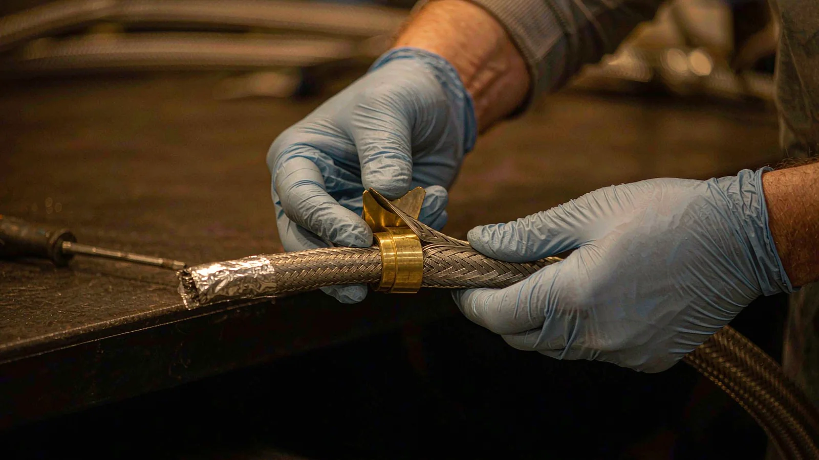
Folded back, not cut short. The braid has to lie over the insert all the way round before the body closes on it.
Verifying the Termination You Made
Three checks, in increasing order of usefulness.
Visual, before closing. Braid folded back over the insert, full circumference, no strands cut, bare metal under the spring, no sealant on the braid.
Continuity, after closing. Screen to enclosure metal, measured at the gland. A continuity buzzer proves almost nothing; a low-resistance reading recorded in the commissioning file at least establishes a baseline for the next visit.
Functional, if the stakes justify it. A transfer impedance measurement per IEC 62153-4-3 on a sample assembly, or a comparative emissions check on the finished cabinet.
The middle check is the one that pays for itself, because the value it records turns an invisible bond into a number that can be compared after the next maintenance.
Specifying a 360° Entry
Requirement
What to write
Why
Contact
Circumferential contact spring, brass or stainless body
“EMC gland” alone does not define the mechanism
Cable
Braid or braid-over-foil, with the braid exposed length stated
A foil-and-drain cable cannot deliver the bond
Landing
Masked bare metal pad at the entry, or an earth bar at the gland row
Determines whether the spring has anything to contact
Verification
Recorded screen-to-frame resistance at commissioning
Turns the bond into a measurable baseline
Is a 360° gland worth it on a foil-and-drain cable?
No. The foil cannot be contacted reliably around its circumference and the drain is a single wire, so the termination is a pigtail whatever the gland is called.
Can I bond at the gland and leave the far end floating?
At low frequency, sometimes. Above a few megahertz the open end forces the return current elsewhere and the screen stops working. Bond both ends unless a measured loop problem says otherwise.
Why does the drive only trip at one speed?
That is the signature of a resonance in the return path, and a long pigtail is the usual cause. The screen works below that frequency and not above.
Does the gland body have to be metal?
For a 360° bond, yes. A polyamide gland cannot carry the screen current, whatever insert is fitted inside it.
How do I know the spring is still making contact after five years?
Measure it. A resistance recorded at commissioning is the only way to tell whether a later value is normal or a deterioration.
Send the cable construction, the drive or signal type and a photograph of the entry plate, and we will say whether the screen can be bonded at the gland or the cable has to change. The EMC gland overview covers the product side; the installation guide covers the assembly sequence.
Brass is the default body material for industrial cable entry, but it is not the universal answer. What brass does well, the four functional families, how to select in five steps, and where brass is the wrong choice.
A cable gland contains two elastomer seals, and they are not always the same compound. Here is how EPDM, NBR and silicone actually differ, where each one fails, and what to put in an enquiry.
Si se dedica a la protección de cables, sabrá lo importante que es un buen prensaestopas impermeable. Piense en los prensaestopas como los héroes anónimos que mantienen su cableado a salvo del agua, el polvo y los daños mecánicos. Especialmente en entornos industriales difíciles, la elección del tipo adecuado de prensaestopas puede [...]
Utilizamos cookies para mejorar su experiencia de navegación, publicar anuncios o contenidos personalizados y analizar nuestro tráfico. Al hacer clic en "Aceptar todo", aceptas el uso que hacemos de las cookies.