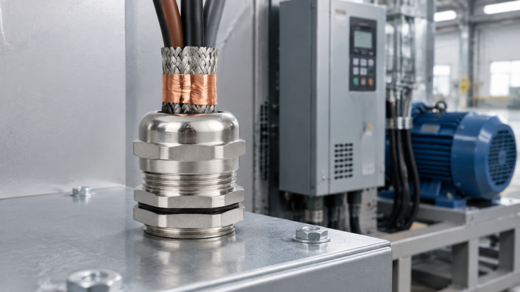
A VFD cable gland has to do three jobs at once: clamp a cable screen to the enclosure around its full circumference, seal against humid plant air, and stay tight on a motor that never stops vibrating. Get one wrong and the failure rarely shows up at the gland — it shows up as an encoder that loses position at low speed, or a bearing that starts fluting after eighteen months.
This guide covers the application side: why the drive end and the motor end ask for different things, how to size a gland for a cable that is fatter than you expect, where the bond path breaks, and what a gland cannot fix.
Why a VFD Motor Cable Is Not Just a Power Cable
A drive does not deliver a sine wave. It switches a DC bus to synthesise a variable-frequency output, and those edges are fast. On a long motor cable they drive a common-mode current that returns through the screen, the motor frame and the building earth rather than the neutral. Above a few hundred kilohertz that current behaves like current on a transmission line, not in a wire. The screen contains it only while it is electrically continuous end to end — break that, or bond it through a thin wire, and the screen becomes an antenna instead of a shield.
What is on the cable
On a 50 Hz supply
On a VFD output
Voltage waveform
Sinusoidal, low harmonic content
PWM switched, fast edges
Dominant frequency content
Fundamental plus low harmonics
Switching frequency plus harmonics into the MHz band
Main interference path
Conducted, mostly differential
Common mode — down the phases, back through screen and frame
What the screen has to do
Little or nothing
Carry high-frequency return current at low impedance
Typical victim
Rarely anything
Encoder and analogue signals, comms, motor bearings
An EMC gland earns its place with three mechanical features, and only the first is about EMC.
A circumferential contact surface shaped to press against a braid or folded tape around the whole cable, as close to the enclosure sheet as the design allows. This is what keeps bond impedance low as frequency rises.
A sealing insert that grips the cable jacket — not the cores — so the IP rating survives thermal cycling.
A strain-relief grip that stays put under vibration, which otherwise works a loose cap nut until contact resistance climbs.
Nickel plating matters more than it sounds: bare brass oxidises in humid air, and a film of oxide on the contact face is a resistor in series with your bond. That is essentially what separates EMC from standard cable glands — a metal body with no shaped contact face is half the job.
The Drive End and the Motor End Are Different Jobs
Every guide says the screen must be bonded at both ends. Fewer point out that the two ends are mechanically different, and that the motor end is where installations usually fail.
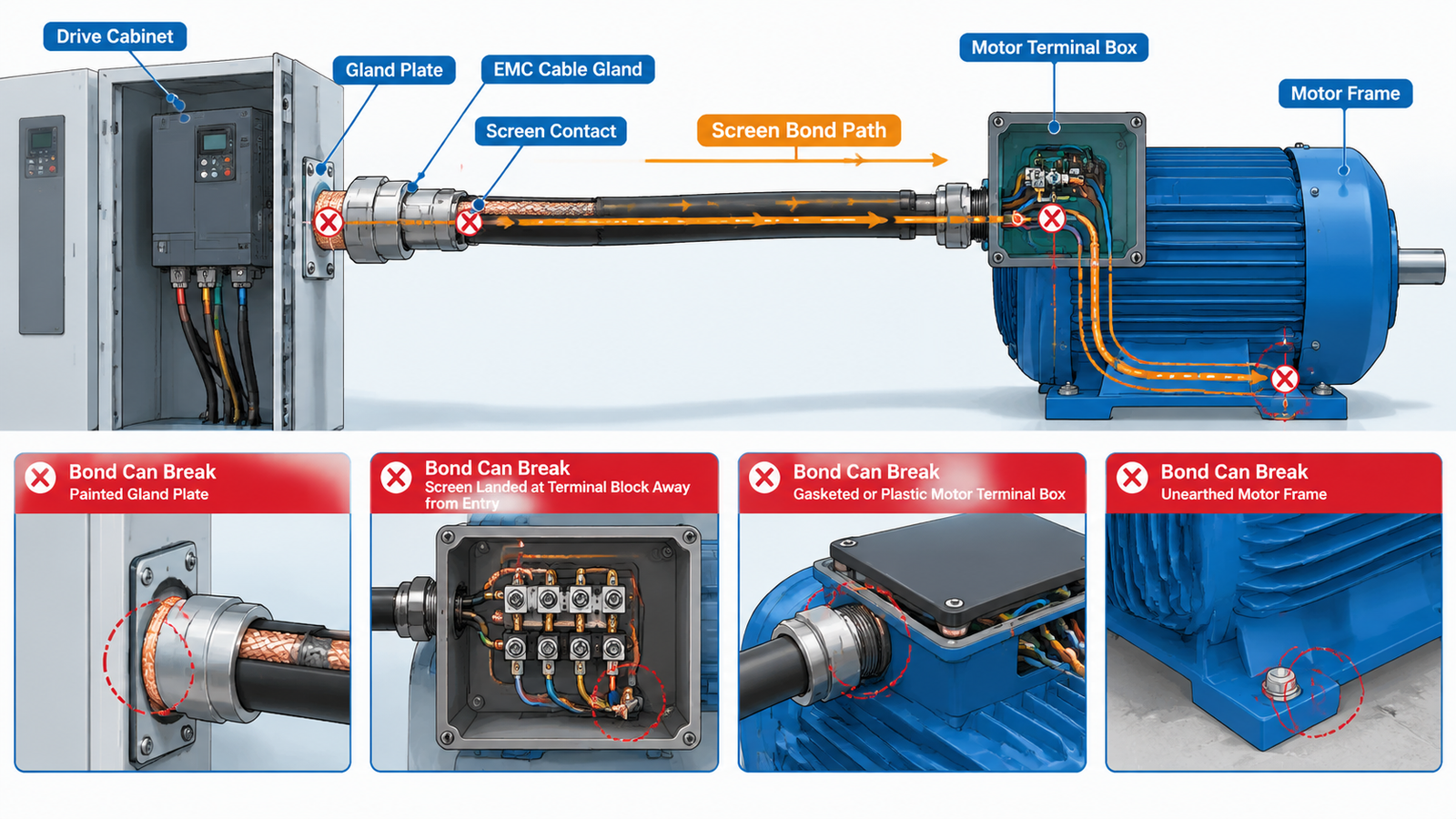
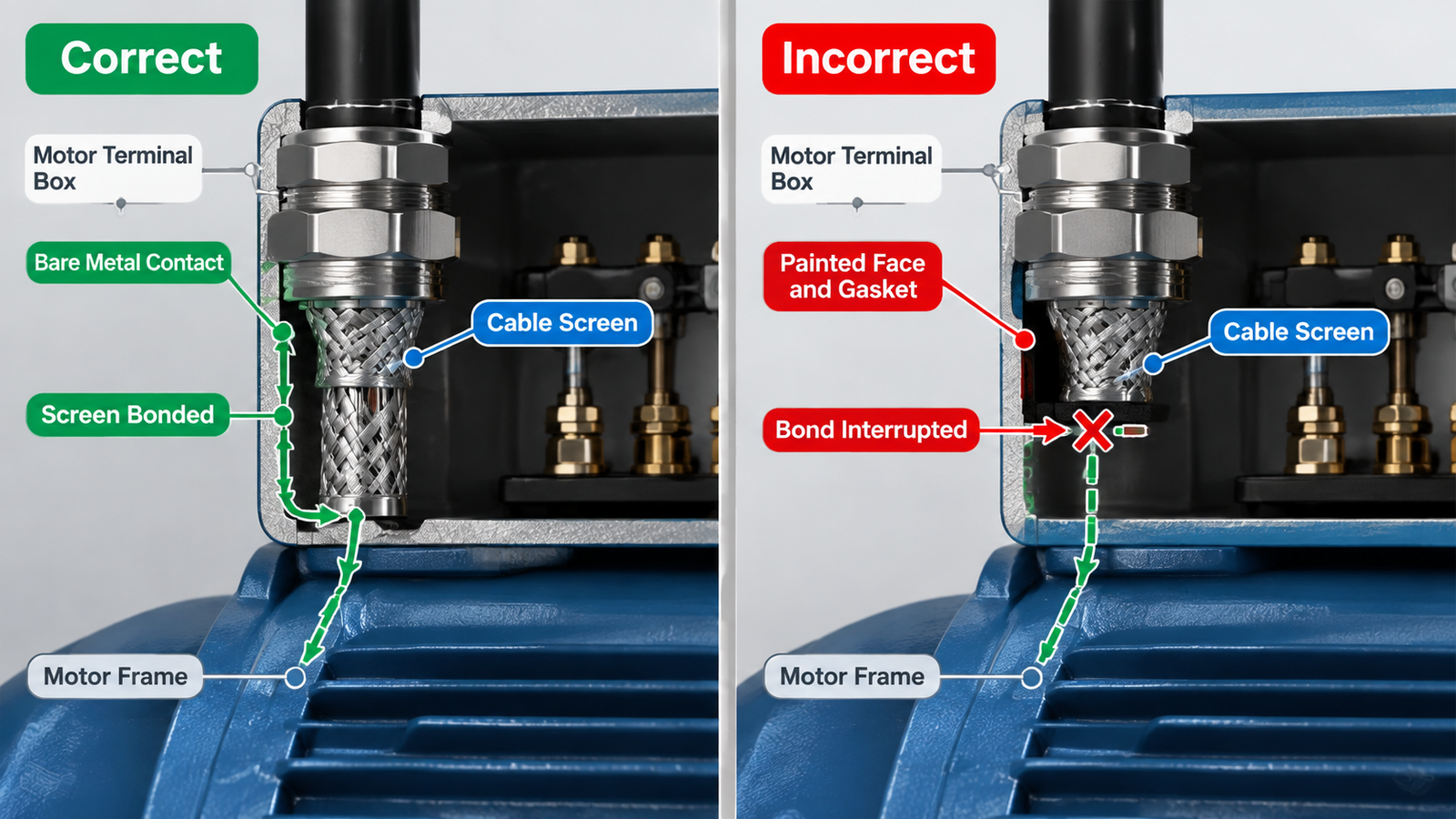
At the drive you are working in a cabinet, with room to dress the screen and test it. At the motor you are working in a small cast terminal box that may sit on a gasket, may be painted inside, and may be plastic on smaller frames. The bond has to travel from screen to gland, gland to box wall, and box to motor frame — and every interface is a place it can stop.
Entry point
What usually goes wrong
What to verify
Drive cabinet gland plate
Powder coat, paint or a gasket trapped under the gland seat
Bare metal at the contact face, or an earth washer that bites through the coating
Inside the cabinet
Screen left long and landed on a terminal block instead of at the entry
The screen is bonded at the entry point, not a metre downstream
Motor terminal box
Gland landed on a painted face, or on a plastic box with no metal path
Continuity from gland body to motor frame, measured rather than assumed
Motor frame to earth
Painted motor feet, isolated mounting, no bonding conductor
A defined low-impedance path from frame back to the drive earth bar
The last row is the one people skip. If the terminal box is not bonded to the frame, the screen path ends at the box and the high-frequency current finds another route — often through a bearing.
Sizing the Gland for Drive Cable
VFD cable is not a standard four-core. It typically carries three phase conductors, symmetrical earth conductors in the interstices, and a copper tape screen under an XLPE or LSZH jacket. That makes it thicker for the same current rating, and the tape you fold back over the sealing cone adds thickness again where the gland clamps.
Measure the jacket outer diameter with a caliper at several points instead of trusting a nominal figure, then choose the gland by where that diameter sits inside its clamping range. Mid-range gives tolerance; sitting on the maximum means the seal insert is fully compressed before the cable heats up and expands.
Because the EMC range covers cable outer diameters from 3 mm to 38 mm across M12 to M63 and PG7 to PG48 threads, the practical question is whether the gland fits the knockout you already have. A step up in cable size often means a step up in thread size: a new hole, a bigger gland plate, or a reducer that adds another interface to the bond path.
Paso
What to do
Why it fails when skipped
Measure the cable
Jacket outer diameter at two or three points, screening or armour included
An undersized gland seals on the cores, not the jacket, and loses the IP rating
Place the fit mid-range
Pick the size where your diameter sits comfortably inside the clamping range
Edge-of-range fits lose seal pressure once the cable is hot and loaded
Allow for the screen fold
Leave strip length for the tape or braid to dress over the cone
Bonding through a stub of braid reintroduces the pigtail you were avoiding
Check the cut-out
Panel hole, thread type and thread length against your plate or box
Metric and PG threads are not interchangeable; neither are their hole sizes
Match the construction
Metal-clad, armoured or braided drive cable needs the gland designed for it
A single-compression gland grips the jacket only and leaves the armour unbonded
Where the Bond Path Breaks After the Gland
Most EMC problems on drive systems are not gland selection problems. They are continuity problems in series with a gland that was chosen correctly.
Break point
Symptom
Correction
Braid twisted into a pigtail
Interference that worsens at higher switching frequency
Dress the screen circumferentially over the cone; remove the pigtail entirely
Gland seated on coated metal
A bond that passes a continuity test and fails at radio frequency
Bare the contact area, or use a toothed earth washer intended to bite the coating
Screen landed at a terminal block
Long unshielded tail re-radiating inside the cabinet
Bond at the cable entry, then run the cores onwards
Stacked glands on one plate
One cable in a pair behaves worse than the other
Check each gland against bare plate metal; shared paint hides the bad one
Cable bent sharply at the entry
Braid or tape damaged and no longer continuous
Respect the bend radius; re-terminate rather than reusing a damaged screen
Cap nut loosened by vibration
Performance that degrades over months rather than at commissioning
Re-check torque at first service; prefer designs that resist back-off
Bond Both Ends — and Understand Why
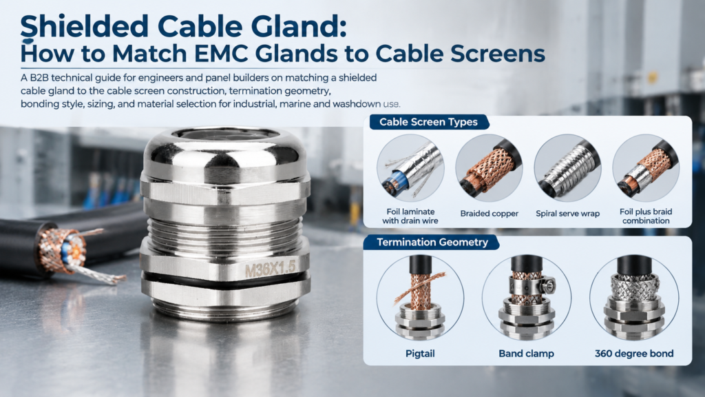
The single-end rule applies to signal circuits, where bonding at both ends creates a ground loop that couples low-frequency noise into a sensitive measurement. A drive motor cable is the opposite case: the interference is high frequency and the return path is the screen itself, so a screen bonded at one end can only re-radiate it. Where a drive manual specifies otherwise, follow the manual. Both approaches are compared in our guide to matching cable glands to different screen constructions.
What a Gland Cannot Fix
Bearing currents. Bonding the screen closes the cable’s return path but does not stop shaft voltage. Fluting is fixed with insulated bearings, a shaft grounding ring or drive-side mitigation — not a better gland.
A cable with no real screen. Unscreened four-core, or foil with a drain wire and no circumferential path, cannot be rescued by any gland.
Excessive motor lead length. Long runs without an output reactor or dV/dt filter generate reflected wave overvoltages regardless of the screen bond.
An unearthed motor frame. The return path has to exist at both ends.
The Field Sequence at the Motor End
The order of operations matters more than the individual steps, because the screen has to be dressed before the gland is tightened, and tested afterwards. Strip the jacket to the length the gland specifies, fold the tape or braid back over the sealing cone without nicking strands, and seat the gland body so it makes metal-to-metal contact with the box wall.
Then measure continuity from the gland body to bare metal on the motor frame, and from the frame back to the drive earth bar. Record the readings before commissioning and repeat them at first service — a bond that deteriorates in service is the classic drive mystery fault. The full procedure is in our walkthrough of how to install an EMC cable gland.
Material and Protection for Motor Environments
Motor rooms bring heat, oil mist, coolant and washdown, and the gland has to survive them long enough for the bond to still be a bond in five years. Plating is a performance feature, not cosmetics.
Medio ambiente
Recommended body
Notas
Indoor control panel, dry
Latón niquelado
Working range to +120 °C; plating keeps contact resistance low in humid air
Machine tool, coolant mist
Latón niquelado
Check seal material against the specific coolant; re-torque at first service
Food, beverage, washdown
Stainless steel 316L
Rated to +200 °C and tolerant of caustic cleaning agents
Outdoor, marine, coastal
Stainless steel 316L
Chloride exposure attacks brass plating within a few years
High ambient near ovens or kilns
Stainless steel 304 or 316L
Nylon is limited to −40 to +100 °C and cannot screen at all
Ingress protection is specified separately from EMC and should be read the same way at every entry. Our glands are tested to IP68 under IEC 60529, and the honest answer to “what does IP68 mean” depends on the declared depth and duration — see the breakdown in how to choose the right IP rating. Stainless steel bodies for harsher motor environments are listed in our stainless steel cable gland range.
Conclusion
A VFD cable gland is a small part doing an unglamorous job: keeping a screen a screen. Choose it by measured cable diameter and by whether the contact geometry presses against the screen around the circumference. Then concentrate on the two things that decide the outcome — bare metal at the gland seat, and a continuous path from screen, through the terminal box, into the motor frame.
If you are specifying glands for a drive panel or an OEM machine series, send us the cable construction and outer diameter per motor size and we will confirm the gland, thread and sealing range that fits, with the documentation your customer will ask for at handover. You can reach the team through our contact page.
PREGUNTAS FRECUENTES
Can I use a standard brass cable gland on a VFD motor cable?
Only if it has a circumferential contact face that presses against the screen. Most standard brass glands are shaped to seal and grip the jacket, with nothing designed to touch the screen. If the only way you can bond it is a pigtail, it is the wrong part.
Should the screen be bonded at both ends on a VFD?
Yes for the great majority of drive installations, at the cabinet entry and at the motor terminal box. The screen carries high-frequency common-mode current back to its source, and that path only works if it is continuous at both ends.
Can I use a nylon cable gland on a VFD motor cable?
Not on screened VFD cable. A nylon body is an insulator and cannot bond a screen under any circumstances. Nylon is reasonable for unscreened control and signal cables in the same panel, provided temperature and UV exposure suit the location.
Does an EMC cable gland stop bearing currents?
No. A correctly bonded gland reduces radiated interference from the motor cable and lowers high-frequency current in unintended paths. It provides no shaft current path, so bearing protection is a separate decision.
How do I check that the screen bond is actually working?
Measure from the gland body to bare metal on the enclosure, then to bare metal on the motor frame, and record the values. That proves continuity and catches the common failures — painted faces, gaskets, plastic boxes, missed earth washers. It does not show how the joint behaves at high frequency, so repeat it at first service.
Match an EMC cable gland to the cable screen: foil, braid, spiral and combination constructions, termination geometry, bonding rules and sizing on jacket OD.
Cuando se trata de instalaciones eléctricas industriales, un prensaestopas no es sólo un conector elegante; es el héroe anónimo que mantiene los cables seguros, sellados y a salvo de los peligros ambientales. Si alguna vez se ha preguntado por qué hay tantos tipos de roscas en estos prensaestopas y cómo elegir la adecuada para su proyecto, este [...]
Cuando se trata de garantizar la seguridad, durabilidad y eficiencia de las instalaciones eléctricas, el humilde prensaestopas desempeña un papel fundamental. Tanto si trabaja en automatización industrial, petróleo y gas, telecomunicaciones o energías renovables, la elección del prensaestopas adecuado puede marcar la diferencia en el rendimiento y la longevidad de sus sistemas. En este artículo, exploraremos [...]
Utilizamos cookies para mejorar su experiencia de navegación, publicar anuncios o contenidos personalizados y analizar nuestro tráfico. Al hacer clic en "Aceptar todo", aceptas el uso que hacemos de las cookies.